Calibration—485/R485 Service
74B. ADJUST B TRIGGERS (Located on Board
Behind B Triggering Switches on Top of Oscillo
scope)
NOTE
To prevent possible interference from the 1 MHz
calibrator signal, set the calibrator FREQ pushbutton
to 1 kHz position during 8 Trigger checks and
adjustments.
a. Set HORIZ DISPLAY to 8; A TIME/DIV to 50
ps; B TIME/DIV to 10 /is; B SOURCE to INT; A & B
COUPLING to AC; A & B LEVEL CW; SWEEP MODE to
AUTO TRIG; VERT MODE to CH 1.
b. Adjust the B triggering by repeating step 73, parts b
through n (substitute the J1063 coax for the J763 coax in
step 73 parts g and i, and substitute the following adjust
ment controls; R1055 for R755, R1075 for R765, R1065
for R775, R1025 for R725, R1020 for R720).
c. Use LEVEL controls to trigger the A and B sweeps;
set HORIZ DISPLAY to ALT; rotate the DTP and check
that the intensified zone of the A trace jumps from cycle to
cycle without movement of the B trace. Disconnect the
Type 191 from the 485.
75A. CHECK EXTERNAL A and B TRIGGERS
a. Set VERT MODE to CH 2; INT TRIG to NORM;
HORIZ DISPLAY to A; SWEEP MODE to NORM TRIG;
A Trigger SOURCE to EXT, CH 2 input to 50 El.
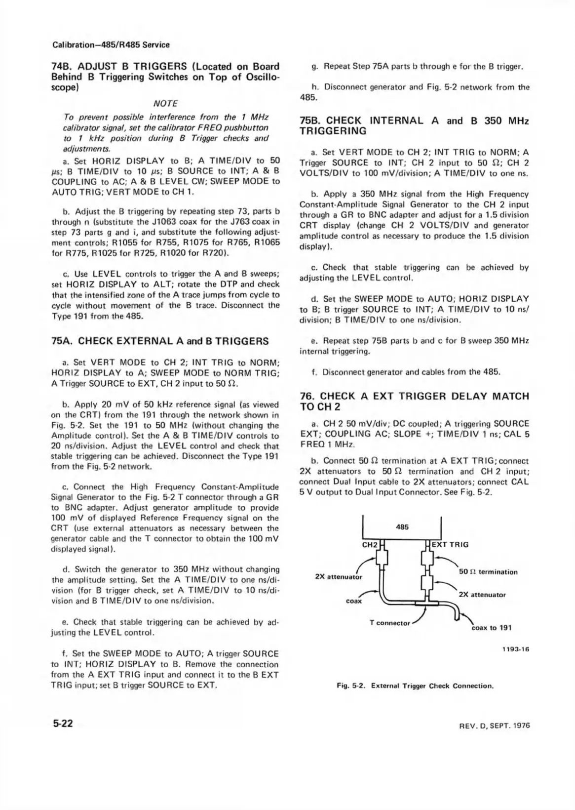
b. Apply 20 mV of 50 kHz reference signal (as viewed
on the CRT) from the 191 through the network shown in
Fig. 5-2. Set the 191 to 50 MHz (without changing the
Amplitude control). Set the A & B TIME/DIV controls to
20 ns/division. Adjust the LEVEL control and check that
stable triggering can be achieved. Disconnect the Type 191
from the Fig. 5-2 network.
c. Connect the High Frequency Constant-Amplitude
Signal Generator to the Fig. 5-2 T connector through a GR
to BNC adapter. Adjust generator amplitude to provide
100 mV of displayed Reference Frequency signal on the
CRT (use external attenuators as necessary between the
generator cable and the T connector to obtain the 100 mV
displayed signal).
d. Switch the generator to 350 MHz without changing
the amplitude setting. Set the A TIME/DIV to one ns/di-
vision (for B trigger check, set A TIME/DIV to 10 ns/di-
vision and B TIME/DIV to one ns/division.
e. Check that stable triggering can be achieved by ad
justing the LEVEL control.
f. Set the SWEEP MODE to AUTO; A trigger SOURCE
to INT; HORIZ DISPLAY to B. Remove the connection
from the A EXT TRIG input and connect it to the B EXT
TRIG input; set B trigger SOURCE to EXT.
g. Repeat Step 75A parts b through e for the B trigger.
h. Disconnect generator and Fig. 5-2 network from the
485.
75B. CHECK INTERNAL A and B 350 MHz
TRIGGERING
a. Set VERT MODE to CH 2; INT TRIG to NORM; A
Trigger SOURCE to INT; CH 2 input to 50 El; CH 2
VOLTS/DIV to 100 mV/division; A TIME/DIV to one ns.
b. Apply a 350 MHz signal from the High Frequency
Constant-Amplitude Signal Generator to the CH 2 input
through a GR to BNC adapter and adjust fora 1.5 division
CRT display (change CH 2 VOLTS/DIV and generator
amplitude control as necessary to produce the 1.5 division
display).
c. Check that stable triggering can be achieved by
adjusting the LEVEL control.
d. Set the SWEEP MODE to AUTO; HORIZ DISPLAY
to B; B trigger SOURCE to INT; A TIME/DIV to 10 ns/
division; B TIME/DIV to one ns/division.
e. Repeat step 75B parts b and c for B sweep 350 MHz
internal triggering.
f. Disconnect generator and cables from the 485.
76. CHECK A EXT TRIGGER DELAY MATCH
TO CH 2
a. CH 2 50 mV/div; DC coupled; A triggering SOURCE
EXT; COUPLING AC; SLOPE +; TIME/DIV 1 ns; CAL 5
FREQ 1 MHz.
b. Connect 50 £2 termination at A EXT TRIG;connect
2X attenuators to 50 El termination and CH 2 input;
connect Dual Input cable to 2X attenuators; connect CAL
5 V output to Dual Input Connector. See Fig. 5-2.
Fig. 5-2. External Trigger Check Connection.
5-22
REV. D. SEPT. 1976