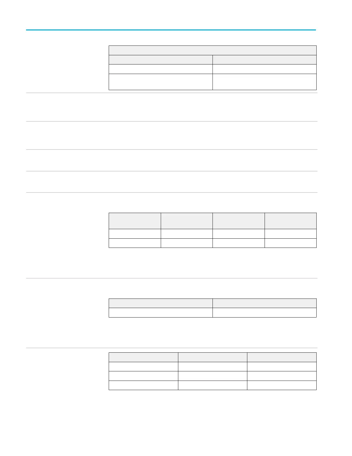
Video-type trigger sensitivity,
typical
Delayed and main trigger
Source Sensitivity
Any input channel 0.6 to 2.5 divisions of video sync tip
Aux In (External) Video not supported through Aux In (External)
input
Lowest frequency for successful
operation of set level to
50 function, typical
45 Hz
Logic-type or logic qualified trigger
or events-delay sensitivities, DC
coupled, typical
1.0 division from DC to maximum bandwidth
Pulse-type runt trigger
sensitivities, typical
1.0 division from DC to maximum bandwidth
Pulse-type trigger width and glitch
sensitivities , typical
1.0 division
Logic-type triggering, minimum
logic or rearm time, typical
For all vertical settings, the minimums are:
Trigger type Pulse width Re-arm time Time between
channels
Logic Not applicable 2 ns 1 ns
Time Qualified Logic 4 ns 2 ns 1 ns
For logic, time between channels refers to the length of time a logic state derived from more than
one channel must exist to be recognized. For events, the time is the minimum time between a main
and delayed event that will be recognized if more than one channel is used.
Minimum clock pulse widths for
setuphold time violation trigger,
typical
For all vertical settings
Clock active Clock inactive
User hold time + 2.5 ns 2 ns
An active pulse width is the width of the clock pulse from its active edge to its inactive edge. An
inactive pulse width is the width of the pulse from its inactive edge to its active edge. The User hold
time is the number selected by the user.
Setup-hold violation trigger setup
and hold time ranges
Feature Min Max
Setup time –0.5 ns 1.0 ms
Hold time 1 ns 1.0 ms
Setup + Hold time 0.5 ns 2.0 ms
Input coupling on clock and data channels must be the same.
For Setup time, positive numbers mean a data transition before the clock.
Specifications (MSO/DPO5000/B Series) Trigger specifications (cont.)
90 MSO70000C/DX, DPO70000C/DX, DPO7000C, MSO5000/B, DPO5000/B Series
 Loading...

