2. Confirm the Probe Compensator signal:
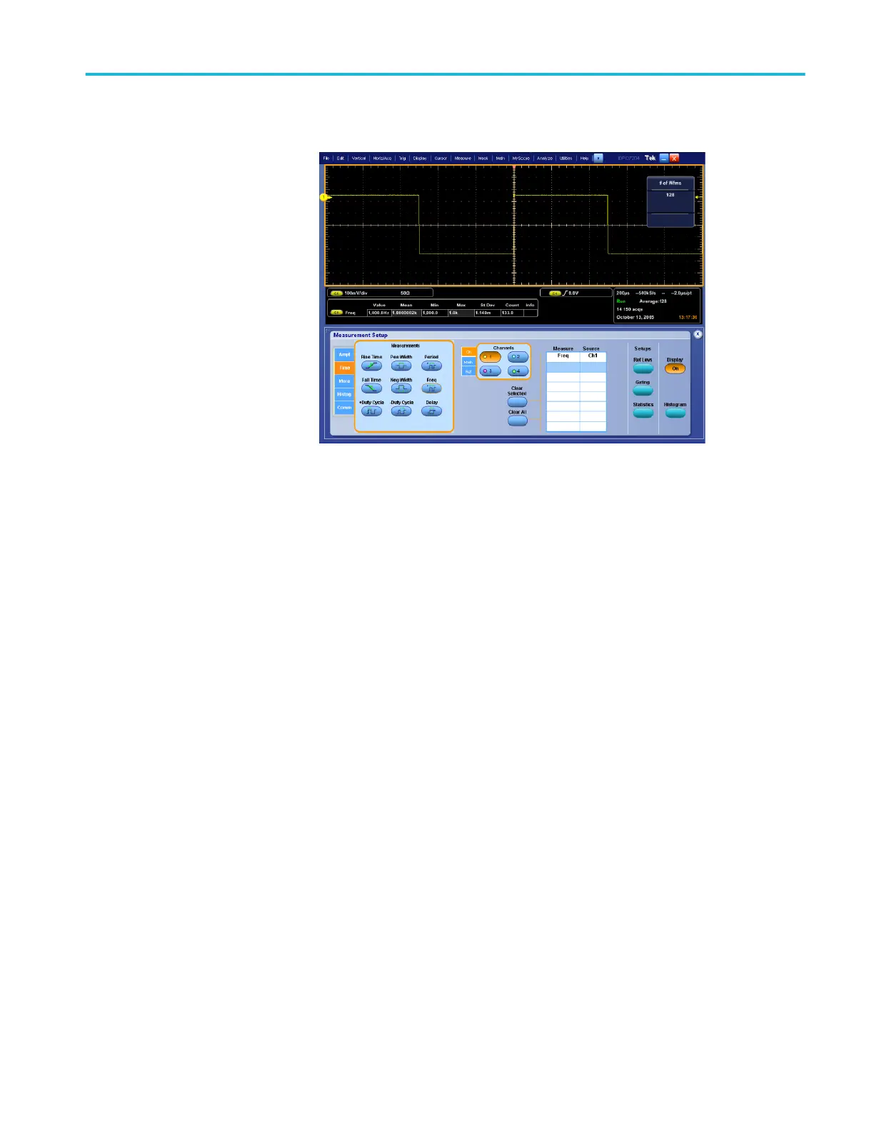
Figure 38: Measurement of probe compensator frequency
a. Save the probe compensation signal in reference memory:
■
From the menu bar, touch File; Save As . . ., Waveform, and then
Ref 1.
■
Touch the Save button to save the probe compensation signal in
reference 1.
■
< 4 GHz models: Disconnect the signal from Ch 1 and the probe
compensation connector.
■
≥ 4 GHz models: Disconnect the signal from Ch 1 and the Fast Edge
connector.
■
Touch File; Recall . . ., Waveform, and then select the file name.
■
Touch the Recall button to recall the probe compensation signal to
the display.
b. Hook up the DC standard source:
■
Set the output of a DC calibration generator to off or 0 volts.
■
Connect the output of a DC calibration generator to Ch 1. Refer to
the following figure.
Performance verification (MSO/DPO70000C, MSO/DPO70000DX, and DPO7000C series)
MSO70000C/DX, DPO70000C/DX, DPO7000C, MSO5000/B, DPO5000/B Series 269
 Loading...

