Getting Acquainted with the Oscilloscope
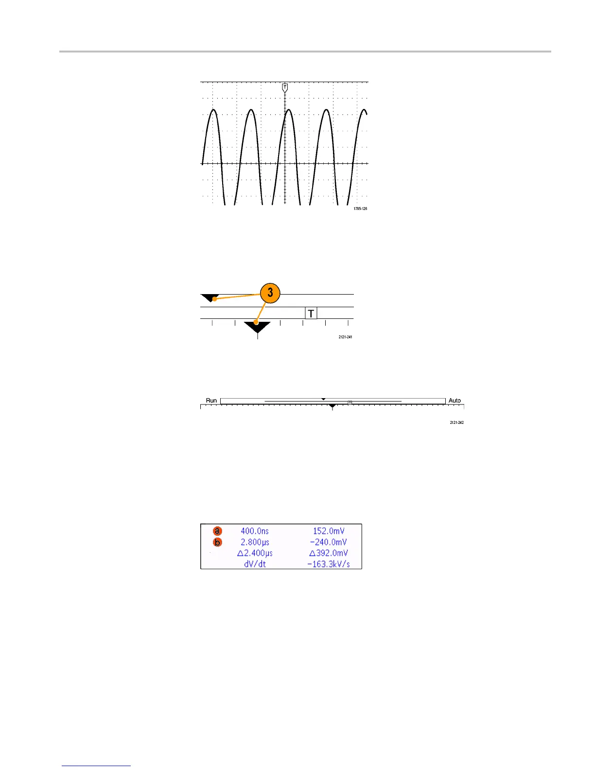
3. The expansion point icon (an orange triangle) shows the point that the
horizontal scale expands and compresses around. To make the expansion
point the same as the trigger point, push Acquire and set the lower menu
Delay item to Off.
4. The w aveform record view shows the trigger location relative to the waveform
record
. The line color corresponds to the selected waveform color. The
brackets show the part o f the record currently displayed on the screen.
5. The trigger status readout s hows trigger status.
6. The s
ecurity icon indicates when the I/O ports are disabled.
7. The cursor readout shows time, amplitude, and delta (Δ) values for each
cur
sor. For FFT measurements , it shows frequency and magnitude. For serial
and parallel buses, the readout shows the decoded val ues.
8. The trigger level icon shows the trigger level on the waveform. The icon color
c
orresponds to the trigger source color.
MDO3000 Installation and Safety Instructions 39

 Loading...


