3. The Results Bar contains controls for displaying cursors, adding result tables to the screen, and adding measurements to
the Results bar. The controls are:
■
The Cursors button displays on-screen cursors. Touch and drag or use the Multipurpose knobs to move the cursors.
Double-tap on a cursor or on the cursor readouts to open a configuration menu to set cursor types and related
functions.
■
The Measure button opens a configuration menu from which to select and add up to four measurements to the Results
bar. Each measurement you add has a separate badge. Double-tap a measurement badge to open its configuration
menu.
■
The Results Table button adds a Measurement, Bus, Search, and Harmonics results table to the screen. The Measure
tab displays all measurements present in the Results bar. The Bus tab displays bus decode information for displayed
bus waveforms. The Search tab displays search event information. The Harmonics tab displays harmonic
measurement results.
■
The Search button lets you detect and mark a waveform where specified events occur. Tap Search to open a Search
configuration menu and set the search conditions for analog and digital channels. Search badges are added to the
Results Bar.
■
The Measurement and Search badges show measurement and search results and are displayed in the Results Bar.
See Badges on page 22.
4. The Settings Bar contains System badges for setting Horizontal, Trigger, Acquisition, and Date/Time parameters; Inactive
Channel buttons to turn on channels; Math/Ref/Bus button to add math, reference, and bus waveforms to the display; and
Channel and Waveform badges that let you configure the individual waveform parameters. Tap a channel or waveform
button to add it to the screen and display a badge. Double-tap a badge to open its configuration menu. See Badges on
page 22.
5. Configuration Menus let you quickly change the parameters of the selected user interface item. You can open
configuration menus by double-tapping on badges, screen objects, or screen areas. See Configuration menus on page 27.
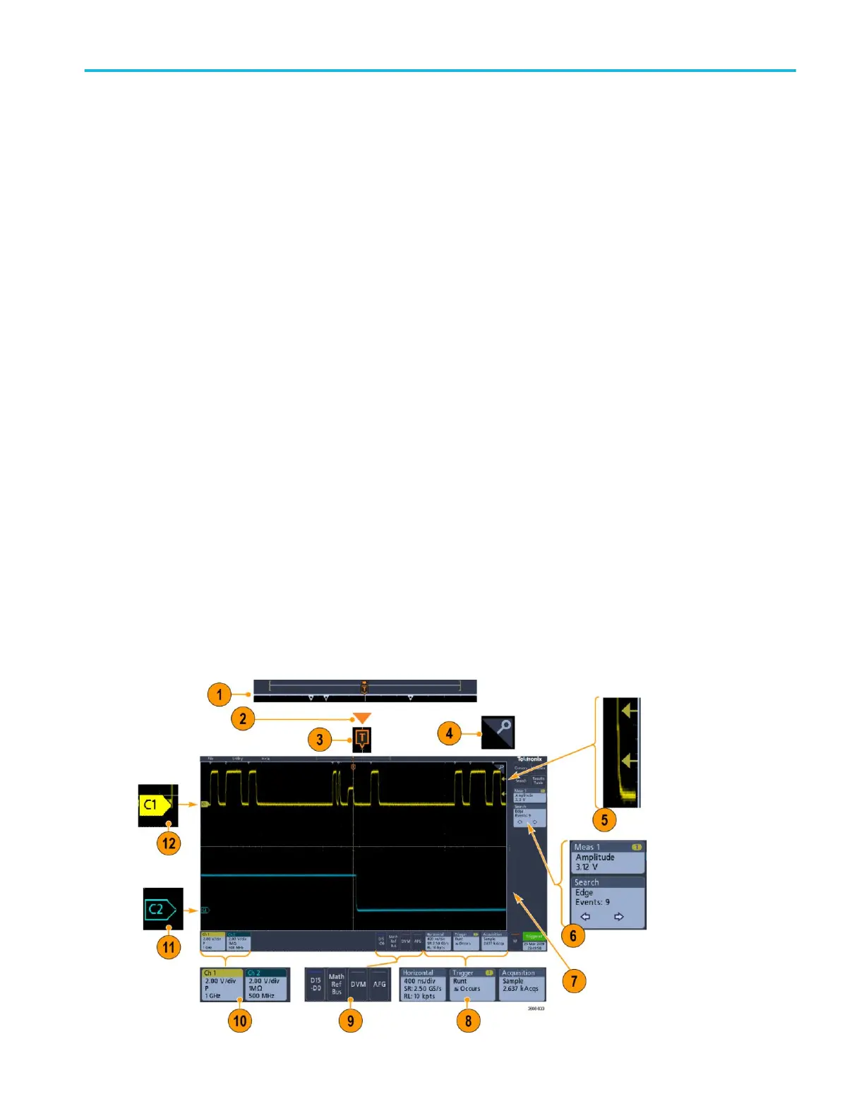
Identifying items in the time domain display
Each area of the user interface has a specific function that helps manage information or controls. This topic shows and describes
the key user interface elements.
Getting acquainted with your instrument
MDO32, MDO34 Installation and Safety Manual 17
ООО "Техэнком" Контрольно-измерительные приборы и оборудование www.tehencom.com
 Loading...


