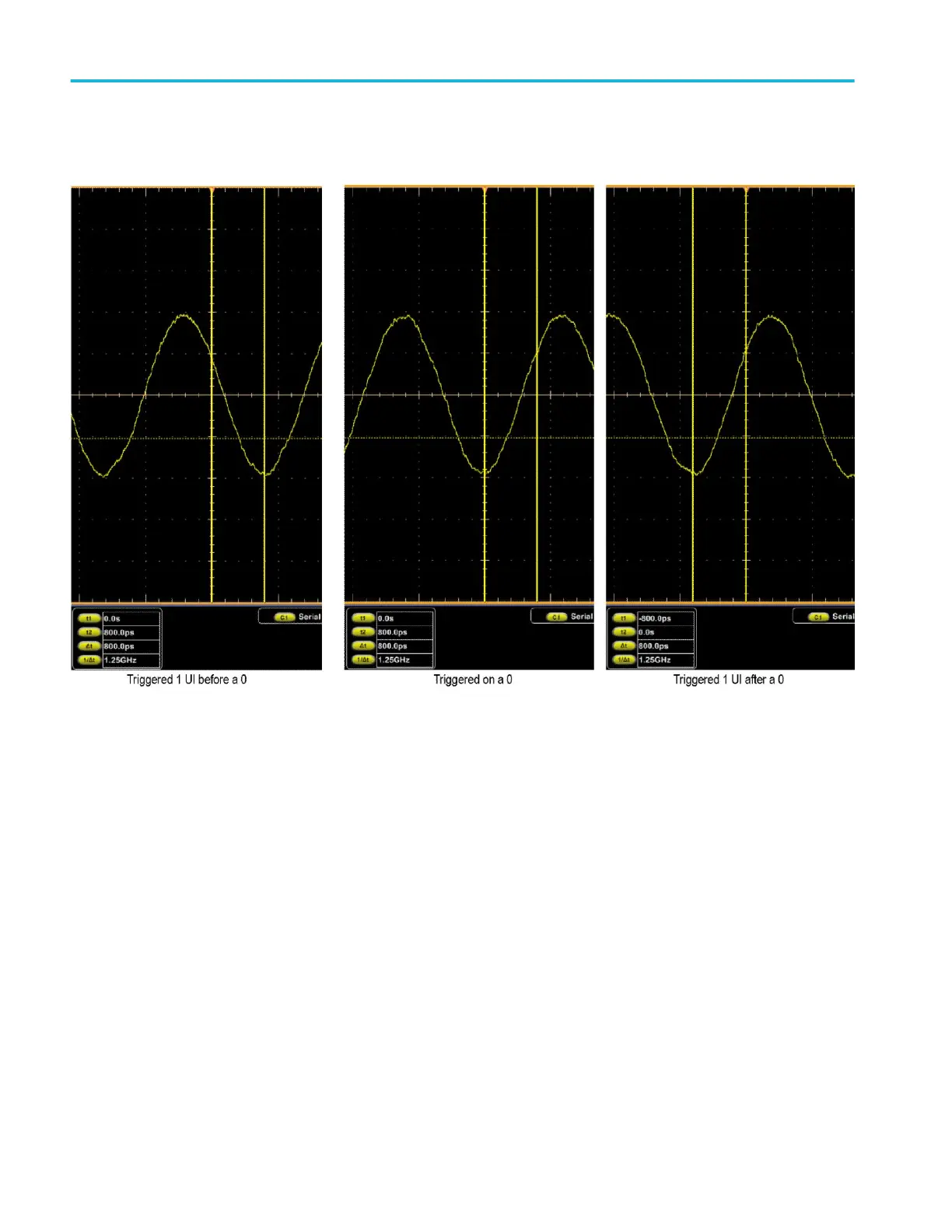
q. Center the Cursor 1 in the low of the waveform nearest the center
graticule line. (See Figure 42: Isolated 0 triggering on page 274.)
Figure 42: Isolated 0 triggering
r. Verify that the instrument triggers at the 0 in the input signal. The
absolute value of the T1 cursor readout must be ≤325 ps. Enter pass or
fail in the test record.
s. Touch the Edit and then the Clear button.
t. Enter data into Serial Pattern Data field for the next setting in the table
that is not yet checked. (See Table 19: Serial pattern data on page 272.)
u. Touch Enter.
v. Center Cursor 1 in the low of the waveform just to the left of the center
graticule line. (See Figure 42: Isolated 0 triggering on page 274.)
w. Verify that the instrument triggers one Unit Interval (UI) after the 0 in the
input signal. The absolute value of the T2 cursor readout must be
≤325 ps. Enter pass or fail in the test record.
Performance verification (MSO/DPO70000C, MSO/DPO70000DX, and DPO7000C series)
274 MSO70000C/DX, DPO70000C/DX, DPO7000C, MSO5000/B, DPO5000/B Series
 Loading...