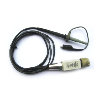
P6139A Instructions
3
Specifications
The characteristics listed in Table 2 apply to a P6139A probe installed on a
Tektronix TDS 3054 oscilloscope unless otherwise noted.
Specifications apply when the instrument warms up for a period of at least
20 minutes in an environment that does not exceed the limits described in
Table 3 on page 4.
Table 2: Electrical characteristics
Characteristic Description
Attenuation
1
10X ±0.5% at DC
Input Resistance
1
10 MW ±0.5%
Input Capacitance 8.0 pF (±0.8 pF)
Compensation Range 8 pF to 12 pF
System Bandwidth (–3 dB) 500 MHz (TDS 3054) or TDS 500 series
100 MHz (TDS 3012)
Maximum Input Voltage
2,3
400 V RMS CAT I or 400 V DC CAT I
300 V RMS CAT II or 300 V DC CAT II
150 V RMS CAT III or 150 V DC CAT III
590 V peak, <50% DF, <1 sec PW
930 V peak, <20% DF, <1 sec PW
1250 V peak, <10% DF, <50 msec PW
See Figure 4 for voltage derating curve.
1
System characteristic.
2
As defined in EN61010-1. See Certifications and compliances in Table 4.
3
RMS=Root Mean Square=rms=The square root of the average of the sum of the
squares of the instantaneous voltage in one cycle = .
300 VDC=300V RMS, 420 V Peak (sinewave)=300 V RMS See Figure 2.
ȍ
(fx
i
)
2
ńn
Ǹ

 Loading...


