PS280 and PS283 Adjustment Procedures
Handheld and Benchtop Instruments Basic Service
21
NOTE. Do not readjust the CURRENT control setting through the remainder of
this procedure.
6. Engage both TRACKING switches (both switches in) so that the power
supply is in the PARALLEL operating mode.
7. Set the SLAVE CURRENT control to maximum (fully clockwise) and set
the SLAVE VOLTAGE control to midrange.
8. Adjust VR502 (Master/Slave circuit board) until a reading of 2 A (PS283) or
4 A (PS280) is displayed on the multimeter.
9. Disconnect the test setup.
5 V Fixed Output Adjustments
Refer to Figures 6 and 10 for the circuit board and adjustment locations used in
this procedure.
To adjust the 5 V fixed output, perform the following steps.
1. Set the digital multimeter to measure a DC voltage of +5.25 V.
2. Connect the digital multimeter to the terminals of the 5 V FIXED 3A output.
3. Adjust VR401 (5 V circuit board) until the multimeter displays 5.00 V
±0.25 V.
4. Disconnect the multimeter from the power supply.
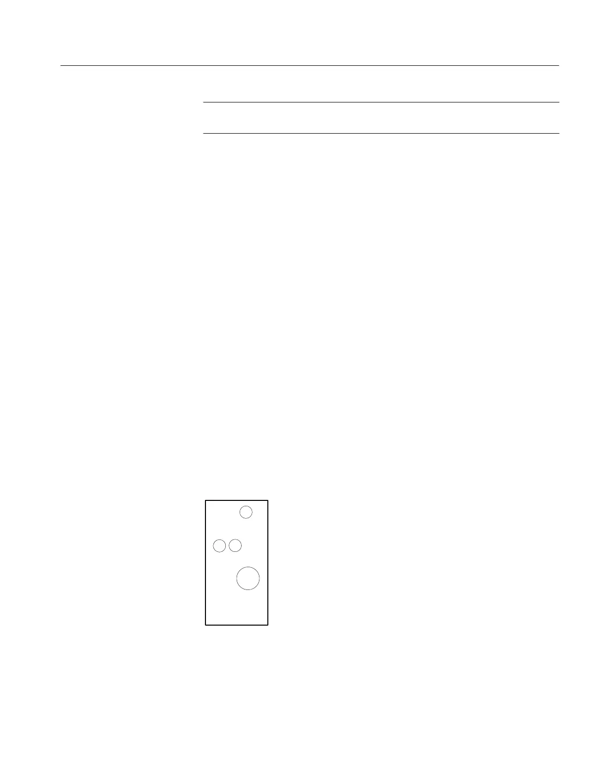
VR401
VR403
VR402
Figure 10: 5 V Circuit Board Adjustments
5 V Output
 Loading...

