TAS 200 Series Performance Verification
10
Handheld and Benchtop Instruments Basic Service
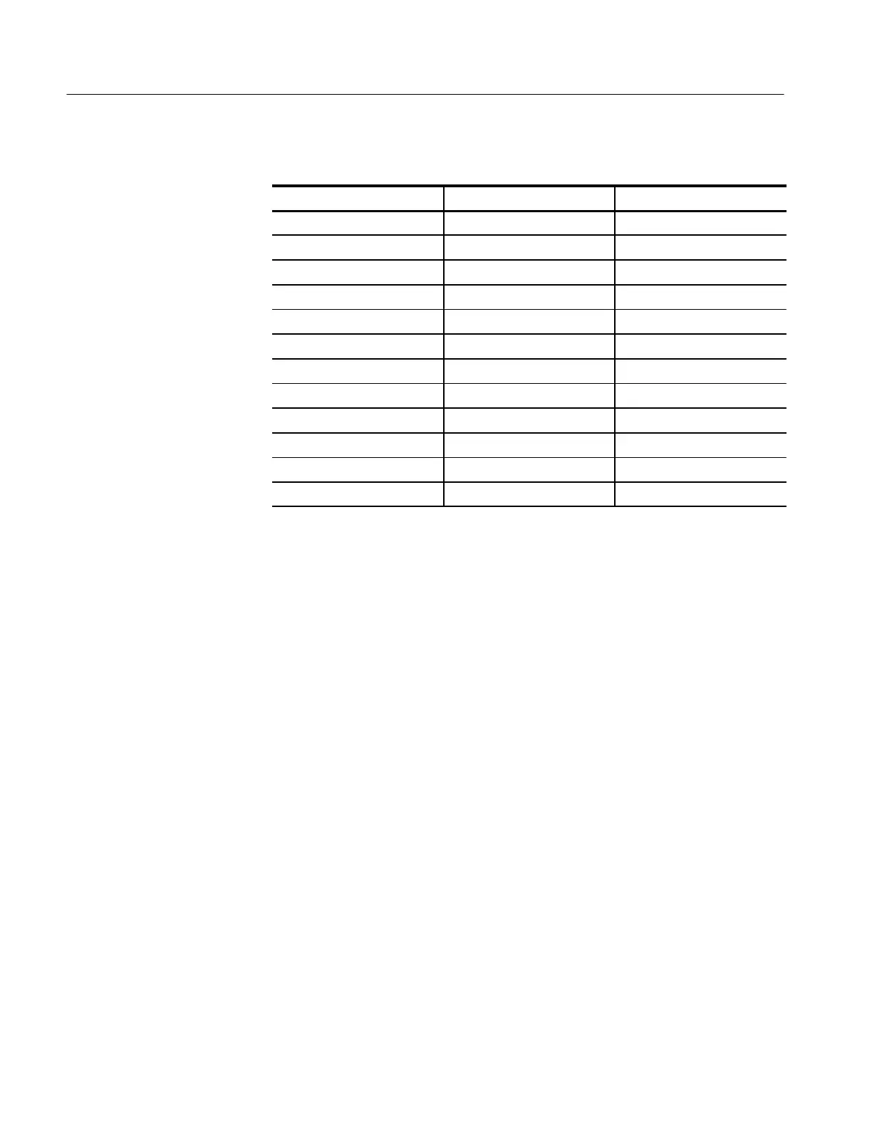
Table 13: DC Gain and Displayed Signal Accuracy
TAS 200 Volts/Div Scale Generator Output Displayed Signal Accuracy
1 mV 5 mV 4.75 to 5.25 div
2 mV 10 mV 4.75 to 5.25 div
5 mV 20 mV 3.88 to 4.12 div
10 mV 50 mV 4.85 to 5.15 div
20 mV 0.1 V 4.85 to 5.15 div
50 mV 0.2 V 3.88 to 4.12 div
100 mV 0.5 V 4.85 to 5.15 div
200 mV 1 V 4.85 to 5.15 div
500 mV 2 V 3.88 to 4.12 div
1 V 5 V 4.85 to 5.15 div
2 V 10 V 4.85 to 5.15 div
5 V 20 V 3.88 to 4.12 div
4. Set the calibration generator output to 5 mV.
5. Return the oscilloscope CH 1 (CH 2) VOLTS/DIV control to 1 mV.
6. Rotate the oscilloscope CH 1 (CH 2) VERTICAL VARIABLE control
counterclockwise off of the CAL position until the amplitude of the
displayed waveform is reduced to two divisions or less.
7. Set the oscilloscope CH 1 (CH 2) VERTICAL VARIABLE control to the
CAL position.
8. Disconnect the test setup from the oscilloscope.
9. Repeat steps 1 through 8 for CH 2.
 Loading...

