TAS 200 Series Performance Verification
12
Bench Test Instruments and Handheld Oscilloscopes Basic Service
To check DC coupled bandwidth accuracy, perform the following steps.
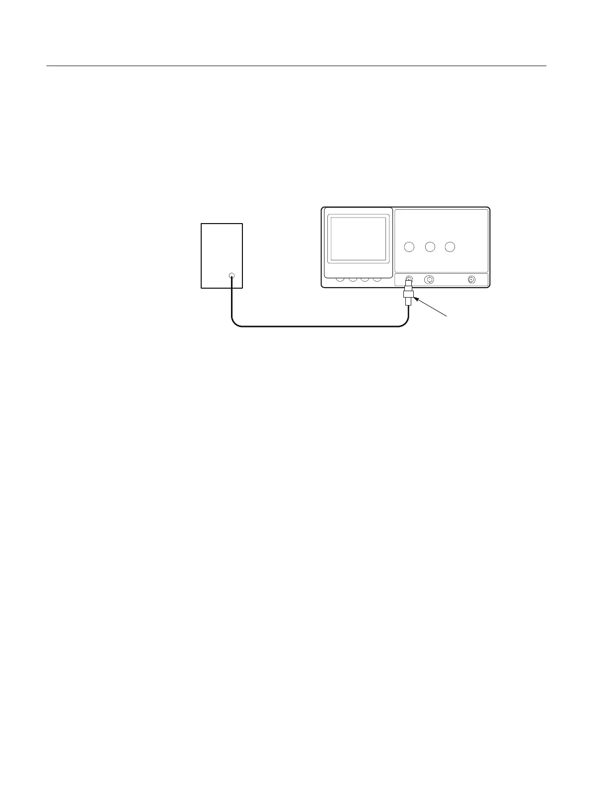
1. Use the 50 Ω precision coaxial cable to connect the output of the leveled
sine wave generator to the 50 Ω termination; then connect the 50 Ω
termination to the TAS 200 series oscilloscope CH 1 (CH 2) input. See
Figure 3 below.
Leveled Sine
Wave Generator
Precision cable 50 Ω Termination
Figure 3: Bandwidth check setup
2. Set up the oscilloscope as follows:
VERTICAL MODE CH1 (CH2)
CH 1 (CH 2) AC-DC DC
CH 1 (CH 2) VOLTS/DIV 1 mV
HORIZONTAL SEC/DIV 10 s
TRIGGER M ODE AUTO
TRIGGER COUPLING DC
TRIGGER SOURCE CH 1 (CH 2)
CH 1 (CH 2) GND Out (release)
3. To confirm the bandwidth of the input channel, perform the following
substeps (a. through c.) at the settings and limits noted in Table 14.
a. Set the oscilloscope CH 1 (CH 2) VOLTS/DIV control as indicated.
b. Set the leveled sine wave generator to the specified 50 kHz reference
amplitude.
c. Verify that the oscilloscope display amplitude remains greater than the
bandwidth minimum amplitude (minimum number of divisions), while
increasing the leveled sine wave generator frequency to the specified
value for the CH 1 (CH 2) VOLTS/DIV setting and oscilloscope model.
DC C oupled Bandwidth
 Loading...

