TAS 200 Series Adjustment Procedures
34
Bench Test Instruments and Handheld Oscilloscopes Basic Service
Instrument
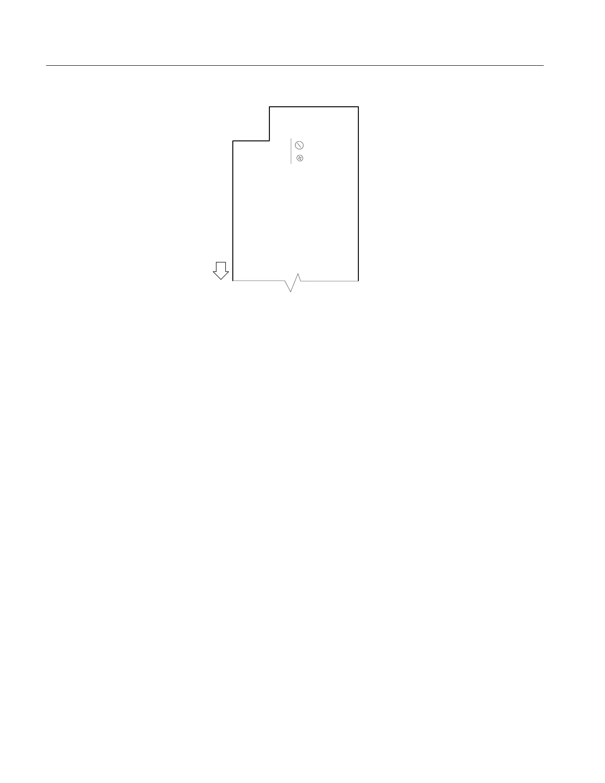
front
3RD COMP
VC301
VR302
Figure 9: Power and High Voltage boar d ( v iewed from the instr ument bottom )
7. Adjust VR107 (VR207) to optimize the waveform flatness. See Figure 8 for
the adjustment locations.
8. Readjust VR103 (VR203) to reduce peak aberrations to less than 0.24 divi-
sions while maintaining peak-to-peak aberrations less than 0.36 divisions.
See Figure 8 for the adjustment locations.
9. Connect a 50 kHz sine wave to the CH 1 (CH 2) input. Adjust the generator
output to produce a waveform six divisions in amplitude on the display.
10. Increase the frequency to 20 MHz for the TAS 220 or 50 MHz for the
TAS 250. Verify that the waveform amplitude exceeds 4.2 divisions at these
frequencies.
11. Set the oscilloscope CH 1 (CH 2) VOLTS/DIV to 1 mV and the sine wave
generator to 50 kHz. Adjust the generator output to produce a waveform
eight divisions in amplitude on the display.
12. Increase the frequency to 10 MHz for the TAS 220 or 15 MHz for the
TAS 250. Verify that the waveform amplitude exceeds 5.6 divisions at these
frequencies.
13. If steps 10 or 12 fail the specified criteria, repeat steps 7, 8, and 9.
14. Set the VERTICAL MODE to CH2 and repeat steps 2 through 13 for CH 2.
 Loading...

