PS2520 Series Adjustment Procedures
64
Handheld and Benchtop Instruments Basic Service
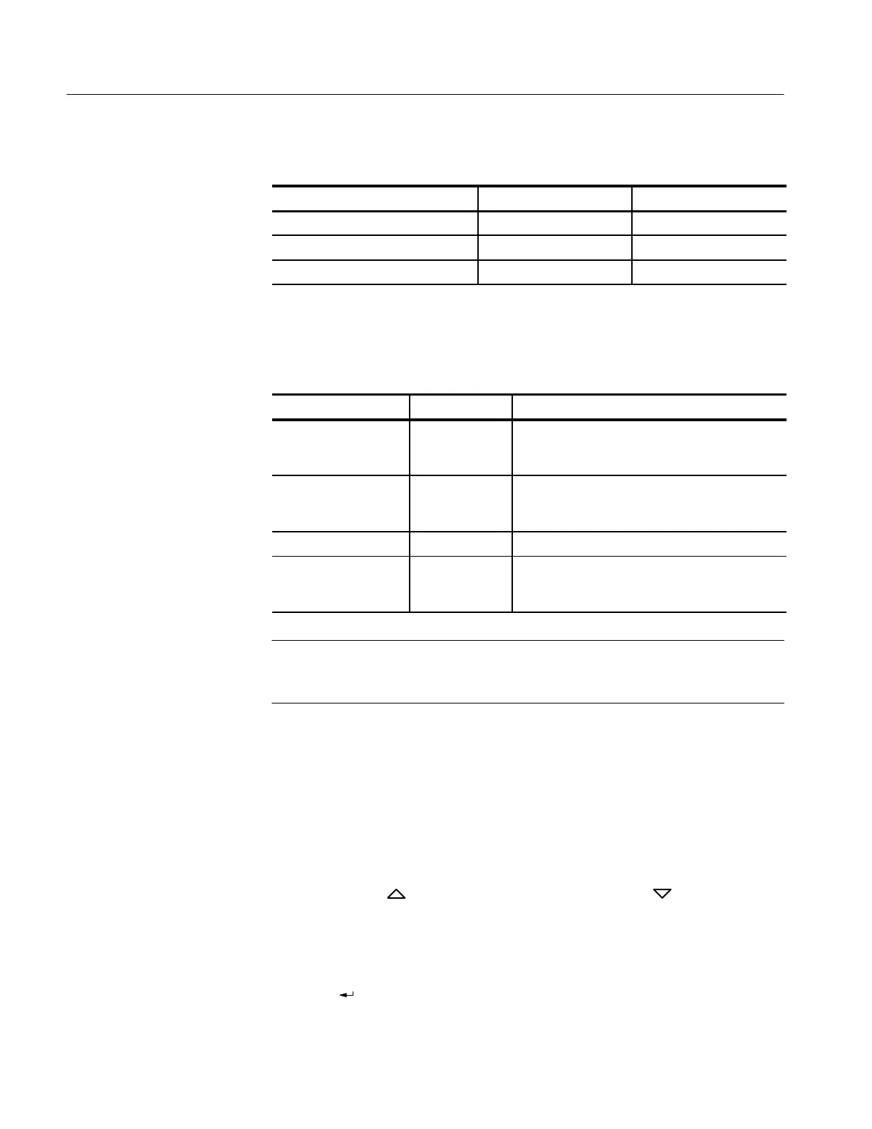
Table 12: Set DMM Function and Range
Calibration Type DMM Function DMM Range
All voltage calibrations DC Volts Autorange
Current offset DC Amperes 2 A
Current full scale DC Amperes 10 A
6. Connect the DMM to the power supply as outlined in table 13.
Table 13: DMM to Power Supply Connections
Calibration Type Display Code Connection Instructions
Voltage cL10, cL11 Connect DMM positive and negative leads to the
corresponding power supply (+) and (–) OUTPUT
terminals.
Current cL20, cL21 Connect DMM positive and negative leads to the
corresponding power supply (+) and (–) OUTPUT
terminals.
Overvoltage Protection cL30, cL31 No connection from DMM to power supply.
Parallel Output Current cL40, cL41 Connect DMM positive and negative leads to the
corresponding power supply (+) and (–) OUTPUT
terminals.
NOTE. The DMM range and function must be properly selected before proceed-
ing to the next step. Ensure that good connections exist between the DMM and
the power supply.
7. Enter the calibration mode on the keypad:
a. Press 1 for voltage calibrations.
b. Press 2 for current calibrations.
c. Press 3 for overvoltage protection calibrations.
d. Press 4 for parallel output calibrations.
8. Press VOLTS
for offset calibration, or press VOLTS for full-scale
calibration.
9. Verify that the readout displays the correct code for the desired calibration.
See Table 10.
10. Press (
) on the power supply keypad to initiate the calibration. Refer to the
instructions below to complete each calibration.
 Loading...


