THM500 Series Performance Verification
Handheld and Benchtop Instruments Basic Service
19
f. Observe the DV readout on the THM500 series instrument display and
verify that its absolute value falls within the range listed in the fourth
column.
Table 10: Vertical Accuracy Test Settings
THM500 Series
Vertical Scale
DC Voltage Source
(First Cursor)
DC Voltage Source
(Second Cursor)
Instrument DV Readout
(Ignore Polarity)
5 mV/div –15mV +15 mV 27.5mV to 32.5 mV
100mV/div –300 mV +300 mV 552 mV to 648 mV
1 V/div –3 V +3 V 5.52 V to 6.48 V
10V/div –30 V +30 V 55.2 V to 64.8 V
100V/div –300 V +300 V 552 V to 648 V
4. If your THM500 series instrument is equipped with two channels, repeat
Step 3 (all tests) above on CH 2.
5. Disconnect the test setup.
The following check assesses the analog bandwidth.
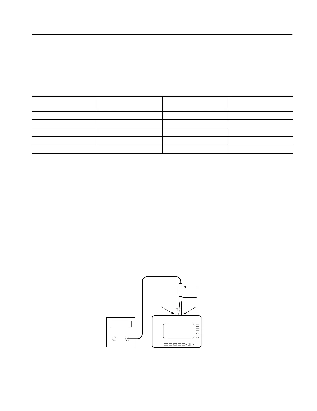
1. Connect the leveled sine wave generator output to the THM500 series
instrument CH 1 and COM inputs. Use a 50 W termination as shown in
Figure 8. Assure that the ground connection for each adapter connects to the
common (or ground) connector of its associated instrument.
2. Press the THM500 series instrument CURSORS/TRIGGER button until
the readout shows TRIG in the lower-right corner; then use the
Y
and
B
buttons to set the trigger level to center screen.
THM5xx
CH 1COM
50 termination
50 cable
Leveled Sine
Wave
generator
BNC to dual banana cable
Figure 8: Analog Bandwidth Test Setup
Analog Bandwidth
 Loading...


