Acquiring and Displaying Waveforms
TDS 684A, TDS 744A, & TDS 784A User Manual
3–13
Offset. Use offset to subtract DC bias before examining a waveform. For example,
you might want to display a small ripple (for example, 100 mV of ripple) on a
power supply output (for example, a +15 V output). Adjust offset to keep the ripple
on screen while setting the vertical scale sensitive enough to best display the ripple.
To adjust offset, press VERTICAL MENU ➞ Offset (main). Then use the
general purpose knob or keypad to set the vertical offset. Press Set to 0 V (side)
if you want to reset the offset to zero.
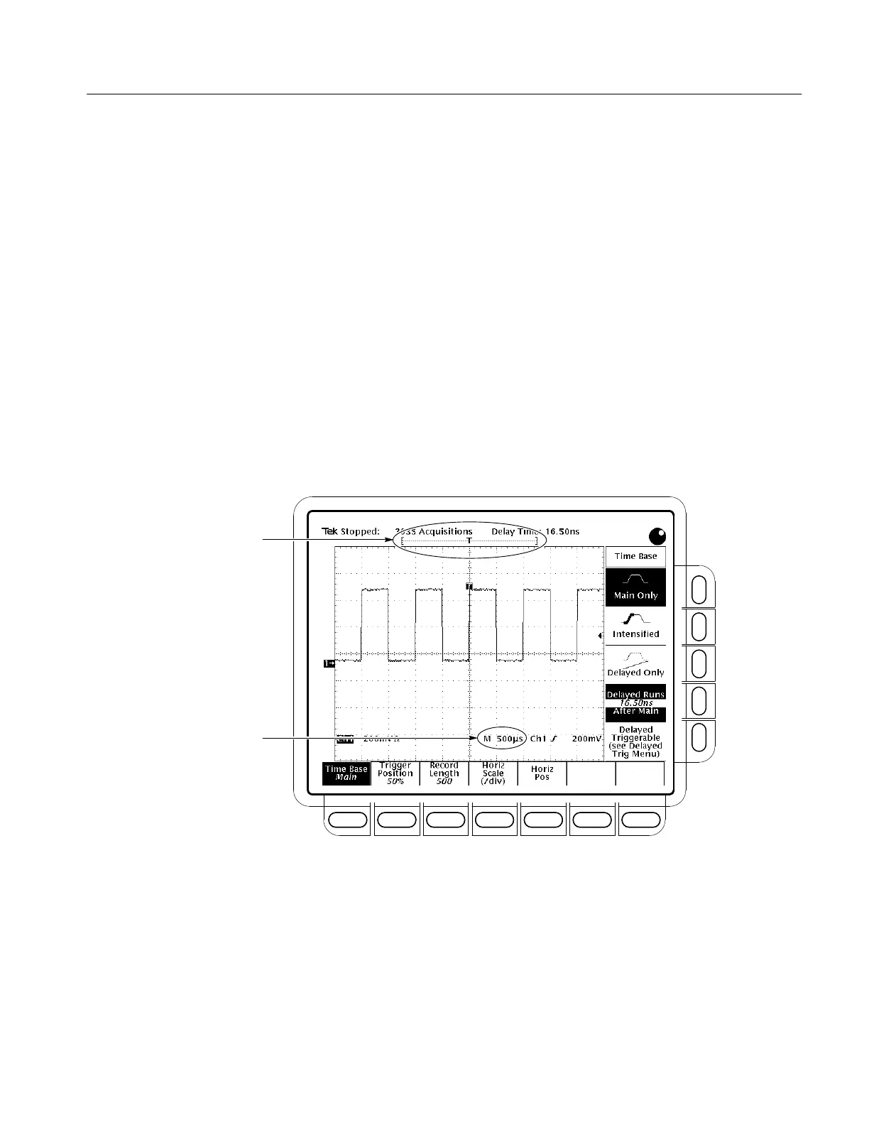
Check the Record View to determine the size and location of the waveform
record and the location of the trigger relative to the display. (See Figure 3–7.)
Check the Time Base readout at the lower right of the display to see the
time/division settings and the time base (main or delayed) being referred to. (See
Figure 3–7. Also see Figure 3–5 on page 3–10.) Since all live waveforms use the
same time base, the oscilloscope only displays one time base and time/division
setting for all the active channels.
Record View Readout
Time Base Readout
Figure 3–7: Record View and Time Base Readouts
The TDS Oscilloscope provides control of horizontal position and scale using
either the horizontal front panel knobs.
By changing the horizontal scale, you can move the waveform right or left to see
different portions of the waveform. That is particularly useful when you are
using larger record sizes and cannot view the entire waveform on one screen.
To Check the
Horizontal Status
To Change Horizontal
Scale and Position
 Loading...


