Acquiring and Displaying Waveforms
3–18
TDS 684A, TDS 744A, & TDS 784A User Manual
A TDS 700A model oscilloscope (the TDS 684A uses only real time sampling)
uses equivalent time sampling to extend its sample rate over its real-time
maximum sampling rate, but only under two conditions:
You must have turned equivalent-time on in the Acquisition menu.
You must have set the oscilloscope to a sampling rate that is too fast to allow
it to get enough samples with which to create a waveform record using
real-time sampling.
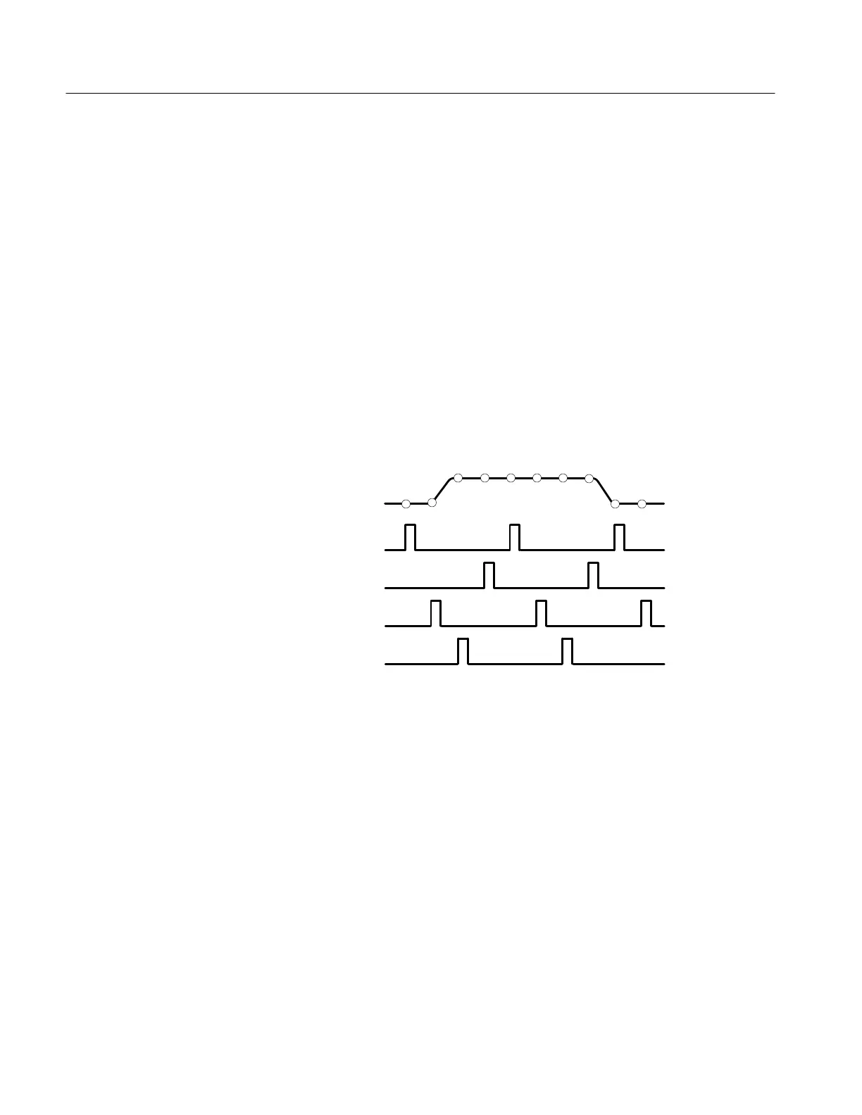
If both conditions are the case, the oscilloscope takes a few samples with each
trigger event and eventually obtains enough samples to construct a waveform
record. In short, the oscilloscope makes multiple acquisitions of a repetitive
waveform to obtain the sample density required for a waveform record. (See
Figure 3–12.) By doing so, the oscilloscope lets you accurately acquire signals
with frequencies much higher than its maximum real-time bandwidth would
allow. Equivalent-time sampling should only be used on repetitive signals.
1st Acquisition Cycle
3rd Acquisition Cycle
nth Acquisition Cycle
2nd Acquisition Cycle
Record Points
Figure 3–12: Equivalent-Time Sampling
The type of equivalent-time sampling the oscilloscope uses is called random
equivalent-time sampling. Although it takes the samples sequentially in time, it
takes them randomly with respect to the trigger. Random sampling occurs
because the oscilloscope sample clock runs asynchronously with respect to the
input signal and the signal trigger. The oscilloscope takes samples independently
of the trigger position and displays them based on the time difference between
the sample and the trigger.
Your oscilloscope can interpolate between the samples it acquires. Like for
equivalent time sampling, it does so only when it cannot obtain all the real
samples it needs to fill up its waveform record. For instance, setting the
horizontal SCALE to progressively faster acquisition rates leaves progressively
shorter time periods for the waveform record. Therefore, the oscilloscope must
sample faster to acquire the samples (record points) needed to fill up the record.
Equivalent-Time Sampling
Interpolation
 Loading...


