Performance Verification
4-12
TDS1000B and TDS2000B Series Oscilloscope Service Manual
Push menu button Select settingSelect menu option
MEASURE
Source Channel under test
Type Mean
*
The test operates without a trigger. To maintain uniformity and to avoid false
triggering on noise, the Ext trigger is the recommended source.
2. Make a spreadsheet approximately as shown in the example in Appendix A.
You only need to enter the values for column A and the equations. The
values in columns B, C, D, E, F, and G are examples of the measured or
calculated values.
The PDF version of the TDS1000B and TDS2000B service manual (which
you can download from the www.tektronix.com Web site), includes an
empty spreadsheet for your convenience. To access and save the test
spreadsheet, see the instructions in Appendix A: Example of a Vertical
Position Accuracy Test Spreadsheet on page A--1.
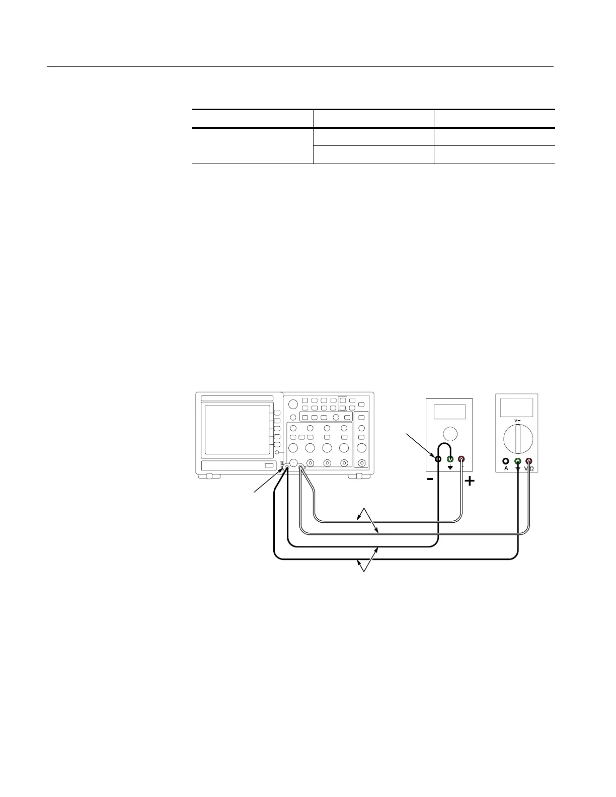
3. Connect the oscilloscope, power supply and voltmeter as shown next.
Power supply
Voltmeter
BNC-to-Dual
Banana adapter
Red leads
Black leads
Negative
Oscilloscope under test
4. Set the power supply to the 1.8 V value shown in column A, the Approxi-
mate Test Voltage.
5. Adjust the vertical position knob for the DC line to position the line in the
center of the screen.
6. Enter the voltage on the voltmeter and on the oscilloscope into the s pread-
sheet in the appropriate columns, B and C.
7. Repeat steps 4 through 6 for the values of 1.76 V through 0 V.
 Loading...

