Performance Verification
TDS1000B and TDS2000B Series Oscilloscope Service Manual
4-11
12. Set the oscilloscope SEC/DIV to 2.5 ns/div.
13. Push SET TO 50%. Adjust TRIGGER LEVEL as necessary and then
check that triggering is stable.
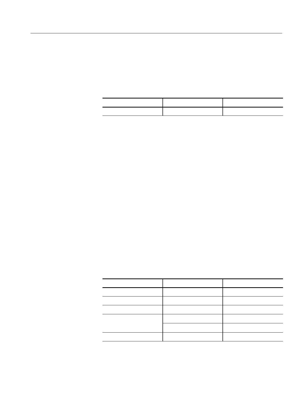
14. Change the oscilloscope setup using the following step:
Push menu button Select menu option Select setting
TRIGGER Slope Falling
15. Push SET TO 50%. Adjust TRIGGER LEVEL as necessary and then
check that triggering is stable.
16. Disconnect the test setup.
The results of this test and the DC Gain Accuracy test together define the DC
Measurement Accuracy of the oscilloscope. The DC Measurement Accuracy
specification encompasses two different ranges of operation over two different
attenuator settings:
H DC Gain Accuracy: Identifies errors, mostly from the A/D converter, when
the vertical position (known as offset in these oscilloscopes) is set to 0
divisions (or a grounded input will show screen center)
H Vertical Position Accuracy: Identifies errors, mostly from the position
control, made when the vertical position is set to a non--zero value
The two attenuator settings operate identically, so verification of the attenuation
range from --1.8 V to 1. 8 V also verifies the attenuation range of --45 V to 45 V.
To set up the test, follow these steps:
1. Set up the oscilloscope as shown in the next table.
Push menu button Select menu option Select setting
DEFAULT SETUP — —
CH 1, CH 2, CH 3, CH 4 Probe 1X
CH 1, CH 2, CH 3, CH 4 Volt s/Div 50 mV/div
TRIGGER
Source Ext*
Mode Auto
ACQUIRE Sample —
Check Vertical Position
Accuracy
 Loading...

