Performance Verification
4-10
TDS1000B and TDS2000B Series Oscilloscope Service Manual
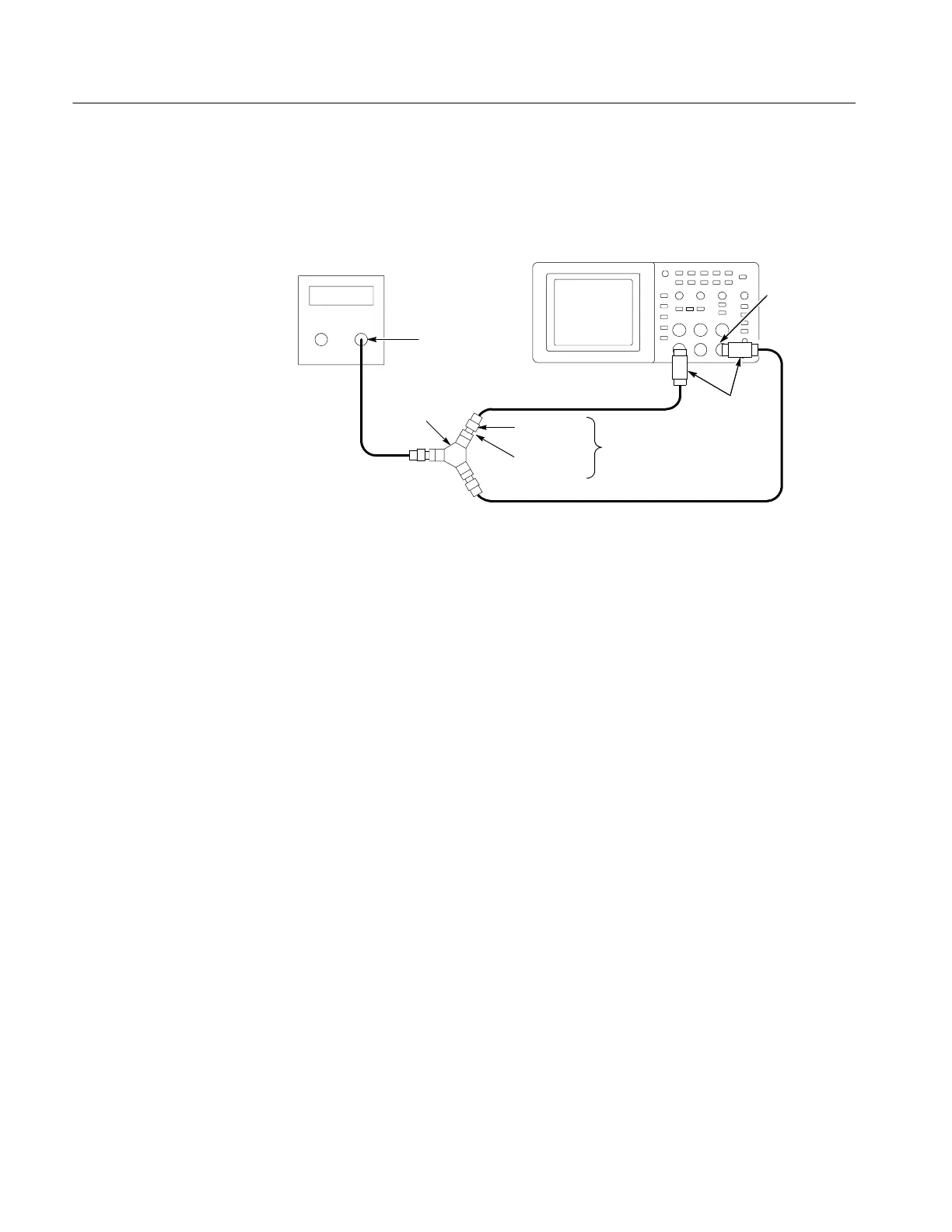
2. Connect the oscilloscope to the leveled sine wave generator as shown below
usingCH1andEXTTRIG.
Digitizing oscilloscope
Leveled sine
wave generator
Output
50 Ω
feedthrough
terminator
Male SMA to
female BNC
SMA female--
to--female
Power divider
3Pieces
EXT TRIG
3. Set the oscilloscope VOLTS/DIV to 100 mV/div.
4. Set the oscilloscope SEC/DIV to 25 ns/div.
5. Set the leveled sine wave generator frequency to 10 MHz.
6. Set the sine wave generator output level to approximately 300 mV
p-p
into
the power splitter. This will be about 200 mV
p-p
on CH1 of the oscilloscope.
The EXT TRIG input will also be receiving approximately 200 mV
p-p
. Small
deviations from the nominal 200 mV
p--p
oscilloscope display are acceptable.
7. Set the leveled sine wave generator frequency to:
H 40 MHz if you are checking a TDS1001B
H 60 MHz if you are checking a TDS1002B, TDS2002B, or TDS2004B
H 100 MHz if you are checking a TDS1012B, TDS2012B, TDS2014B,
TDS2022B, or TDS2024B
8. Set the oscilloscope SEC/DIV to 5ns/div.
9. Push SET TO 50%. Adjust TRIGGER LEVEL as necessary and then
check that triggering is stable.
10. For TDS2022B and TDS 2024B models, set the sine wave generator output
level for a CH 1 display to approximately 350 mV
p-p
.
11. For TDS2022B and TDS2024B models, set the sine wave generator
frequency to 200 MHz.
 Loading...

