iView Integrate
d Measurements
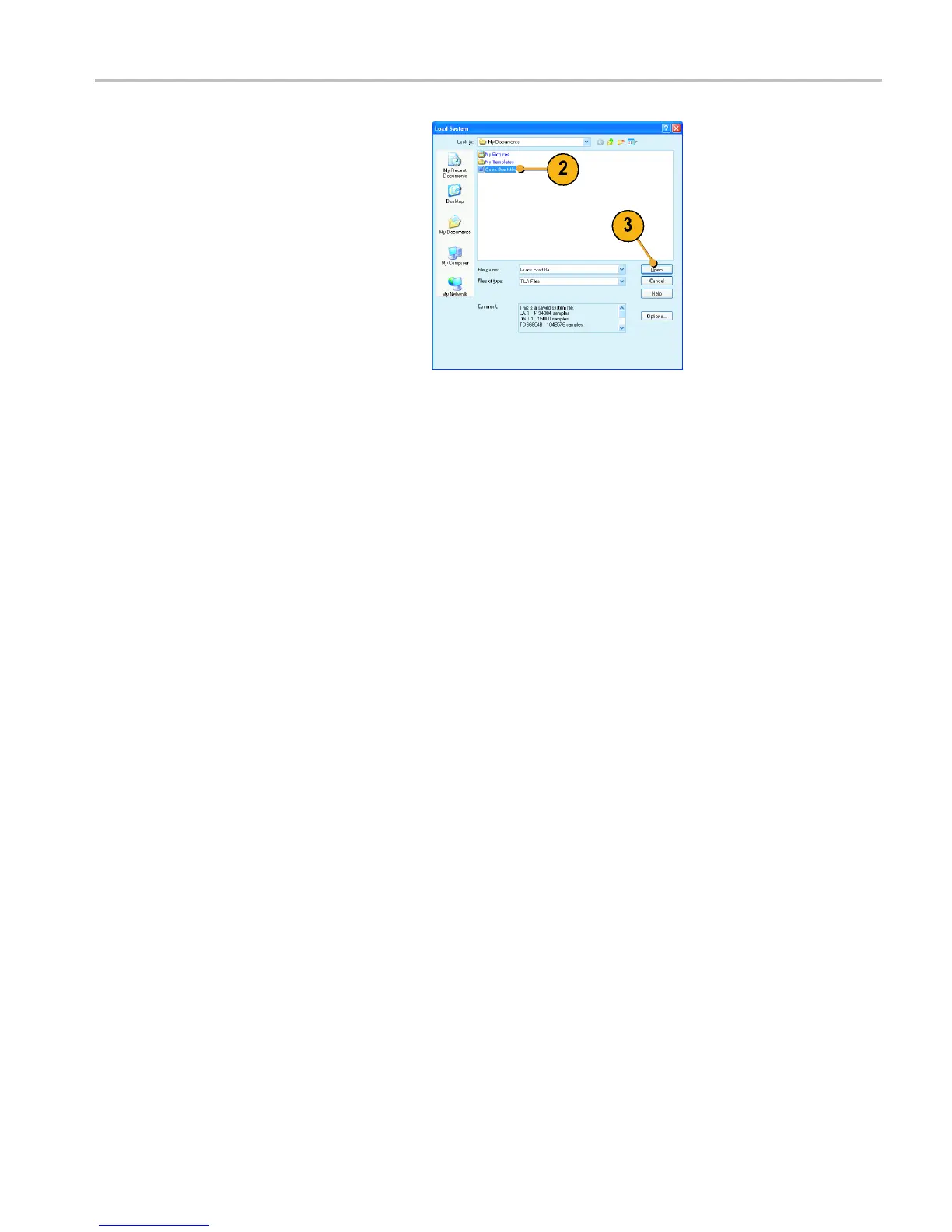
2. Select the file name.
3. Click Open.
4. Click Yes when you are prompted to
confirm your actions.
iView Inte
grated Measurements
You can use the iView feature to connect an external Te ktroni x oscilloscope to the logic analyzer, acquire data from both
instruments, and display the results on the logic analyzer. This is useful for displaying the analog components of a signal in
the same data window as the digital components.
In the following examples the logic analyzer and the oscillo scope will acquire the same data. The logic analyzer captures
the digital components and the oscilloscope captures the analog components.
Use the following steps to set up the oscilloscope for these examples. Refer to the documentation that came with your
oscilloscope for operating instructions.
1. Connect the oscilloscope probe to the same signal source as the logic analyzer (for this example, connect to the
Q output of the flip-flop).
2. Power on the oscilloscope.
3. Press the Default Setup button on the oscilloscope, and then press the Autoset button. You should have a signal on
the oscilloscope screen.
Connecting the Logic Analyzer and the Oscilloscope
After c ompleting the oscilloscope and logic analyzer setups, use the iView wizard to connect the two instruments together.
TLA Quick Start User Manual 29

 Loading...


