GB
32
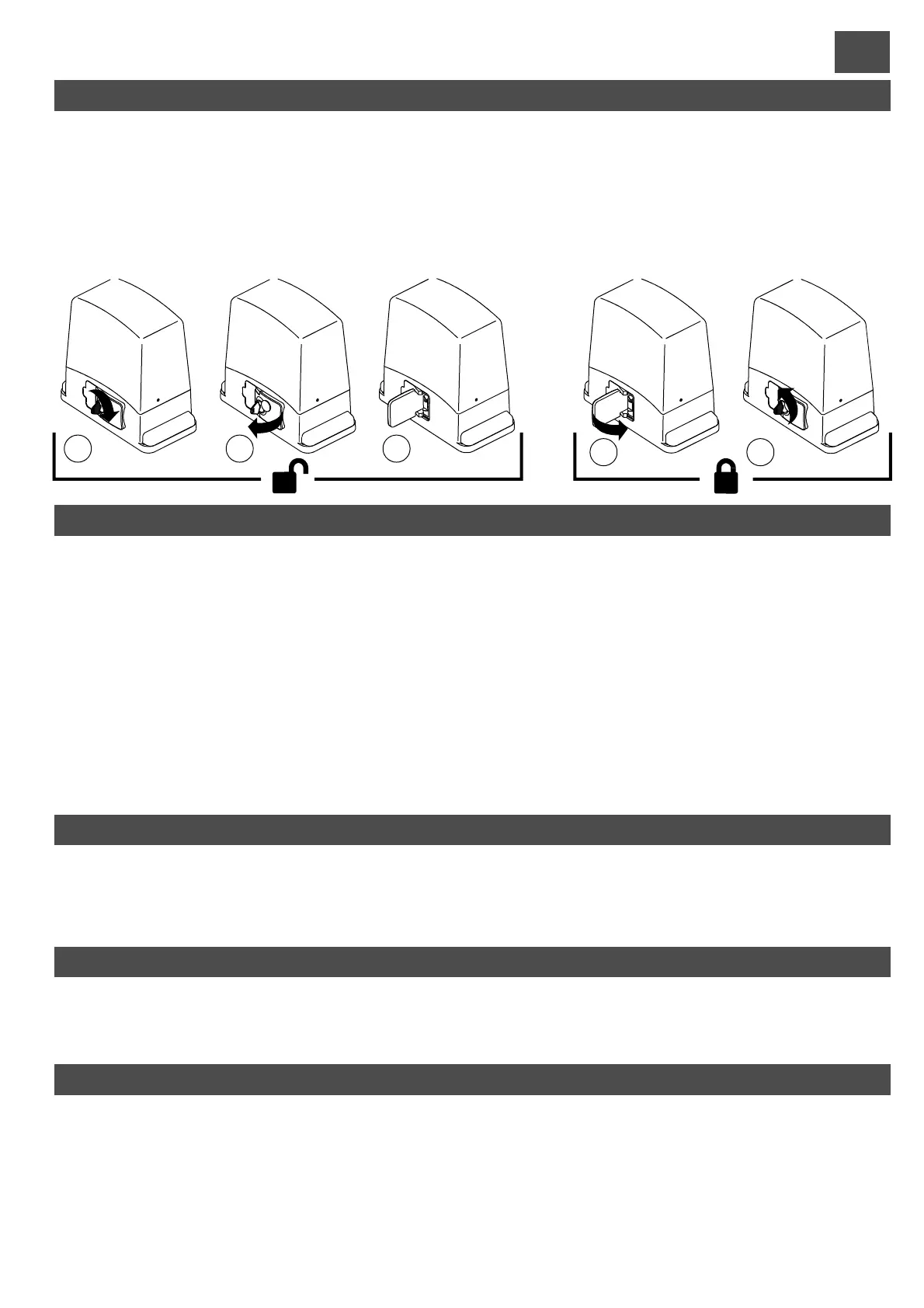
GEAR MOTOR RELEASE AND LOCK PROCEDURE
These two operations are required only in the event of a fault or power failure, and the user or assigned personnel must be
trainedby theinstaller,whoshould provideacopy of these instructions tobe kept withcare togetherwith the releasekey.
1) insert the key and turn clockwise 2) pull the lever through approx. 90° 3) the motor is released and the leaf can
bemoved manually.Tokeep the leaf blocked, proceedas follows.
4) close the lever 5) turn the safety key anti-clockwise; the gearmotor is then locked and the leaf can only be moved
electrically.
Before performing either of these procedures, ensure that the power supply is disconnected from the entire
automation,even in theeventof a power failure.
RELEASE:
LOCK:
1 2 3
4 5
CONTROL UNIT - (fig. I)DESCRIPTION OF PARTS
1) Terminal board for primary transformer connection
2) T
3) 24 V 0.3 A fuse
4) Terminal board for secondary transformer connection
5) Terminal board for limit switch connection
6) STOP/PROG Pushbutton for Programming and Stop*.
7) P/P Step/Step button
8) Trimmer for motor power adjustment
9) Jumper Jp1 (for motor power cut-out and soft-start)
10) Connector for OC2 series receiver
11) Function dip-switch
12) TEST jumper
ransformer mod. RTRA230V10VACAB1
13) Encoder connector
14) Terminal board for low tension connections (24V)
15) ECU reset. Shorting the 2 pins for a moment has the
same effect as switching power off then on again.
16) Indicators LEDs for terminal board inputs. LED on =
input closed
17) Programming LED (L1)
18) Connector for Electric Lock Module
19) Terminal board for 230 V connections
20) Terminal board for mains power supply input
21) 6.3 A fuse for line
22) Terminal board for motor and capacitor connection
* This STOP button must never be considered a safety device, but exclusively a service function to facilitate tests
during installation.
ENCODER
The control unit is equipped with an encoder input. This device allows the gate movement to be adjusted with precision and the anti-
crushingprotectionisguaranteed throughoutgate travel,including deceleration.
During the gate travel programmingstage, if LED L1 flashes, this means the control unit has detected the presence of the encoder. If,
however,LED L1 remains on constantly,thisindicatesthe control unit willnot workcorrectly withtheencoder.
USE OF THE OC2 RECEIVER
Theoperation andprogrammingoftheOC2 series receiver is outlined in theinstructions supplied withthe receiver.
Please note that the receiver channel 1 always corresponds to the step-by-step (P/P) control on the control unit, while channel 2 is
allocatedtothepedestrian control.
PHOTO TEST
For the photo test to work, the system must have two power supply lines for the photocells, the first being connected to terminals 10
and 11, which power the receivers, and the second to terminals 12 and 13, which power the transmitters (the photo test must be
enabled with dip-switch No. 7 in the ON position). The control unit checks the efficiency of the photocells by simulating an activation
at every start of gate movement. If everything is OK the motor starts up, thereby starting the gate movement; if the receiver has any
problemsthecyclestopsandtheopengate light blinks several times to warnof thesituation.
-The photo test also works with photocell2(Jollyinput).
- With the photo test enabled and the control unit in standby, the photocell transmitters are not powered and the FT1 input is open
(LEDoff).Operationofthe photocells may still be checked in this conditionbyshort-circuiting the test jumper (part.12di Fig1).