GB
34
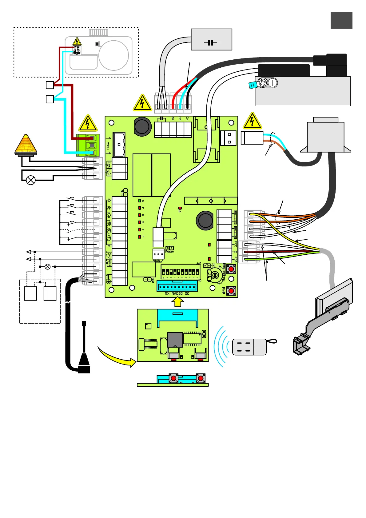
Tipsfor correct Installation:
1)The cross section of the cables shouldbe calculatedaccording to their lengthand absorbed current.
2)Donotuseasinglecableofthe "multi-core" type for all the connections (line, controls,etc.) or in commonwith otherequipment.
3)Useat least twocablesfor theinstallation,e.g.:
cable(A)minimum wire section 1.5 sq.mm
-powersupply line- courtesy/flashinglightline
cable(B)minimum wire section 0.75 sq.mm
-auxiliariespowersupply- controls -safetycontacts.
4)Whenthe control cablesare very long (over50metres),de-coupling isadvisablewith relaysmounted near the control unit.
5) Any N.C. Inputs (photocells, limit switches, fixed safety edge and stops) that are not used In the control unit should be short-
circuited withthecommonterminal terminal.
6)AlltheN.C. contactslinked withthe same inputshould be connected in series.
7)AlltheN.O. contactslinkedwith the same inputshould be connectedin parallel.
F6,3A
230V
1
2
3
4
5
6
7
8
9
10
11
12
13
14
15
16
17
18
19
20
21
22
23
24
27
28
29
30
31
F0,3A
24V
RECEIVER mod. OC2
motor
P1
(P/P)
P2
(PED)
MEMORIA
TRANSMITTER
Rx Tx
Sec. 24Vac (Orange)
230V
Flasher
230V
Courtesy light
OPENING input
PROG.
STOP
P/P
CLOSING input
Step/step input
Stop input
JOLLY input
FT1 Photocell input
Common input
SPIA 24Vac CA
power supply
photocells with
FOTO-TEST
RECEIVER
ANTENNA
Com. Motor (Blue)
ENCODER
230V primary
transformer
Sec. 12Vac (White)
24V (Yellow)
Com. (Brown)
FC(1) Green
FC(2) White
24Vac
EVO1200R
Fuse
F1A
Condensatore
FCC
Ap
Ch
P/P
Stop
Jolly
FT1
FCA
Power
Supply
230V 50Hz
N
L