56
GB
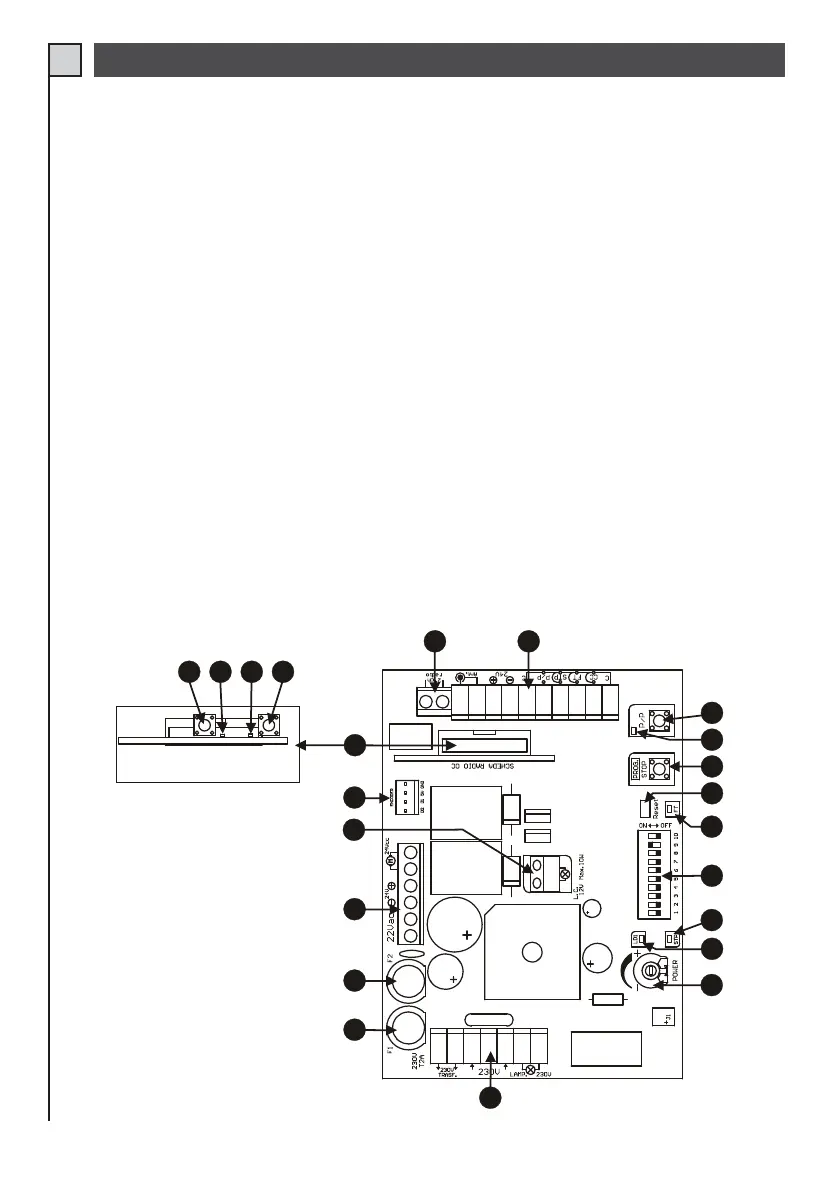
1) 230 V connection terminal board (line, primary transformer and flashing light)
2) T2A 230V line fuse
3) T10A 24V power fuse
4) Motor connection terminal board, 24 V and secondary transformer (22V)
5) Terminal board for courtesy light 12V 10W
6) Encoder connector
7) Connector for optional radio receiver mod. OC.
8) Radio channel 1 programming key
9) Radio channel 1 Led
10) Radio channel 2 Led
11) Radio channel 2 programming key
12) Radio channel 2 output connection terminal board (if available)
13) Connection terminal board for inputs, 24 V and aerial
14) S/S Step-Step pushbutton
15) STEP/STEP input indicator leds. Led off = input open
16) PROG button for Programming and Stop*
17) Control unit reset. Short the 2 pins briefly to cut off and restore power on the control unit.
18) PHOTOCELL input indicator leds. Led lit = input closed
19) Function Dip-switches
20) STOP input status indicator led lit = input closed
21) Programming Led (LD1)
22) Trimmer for power adjustment.
(*) This STOP pushbutton must never be considered a safety device, but exclusively a service function to facilitate testing during installation.
PART DESCRIPTION (fig. 14)
22
5
19
18
20
1312
6
21
17
16
14
15
8
9
10
11
4
3
2
1
Z124
P1
P2
Radio RX mod. OC (optional)
7
Fig. 14