57
GB
Mor n.
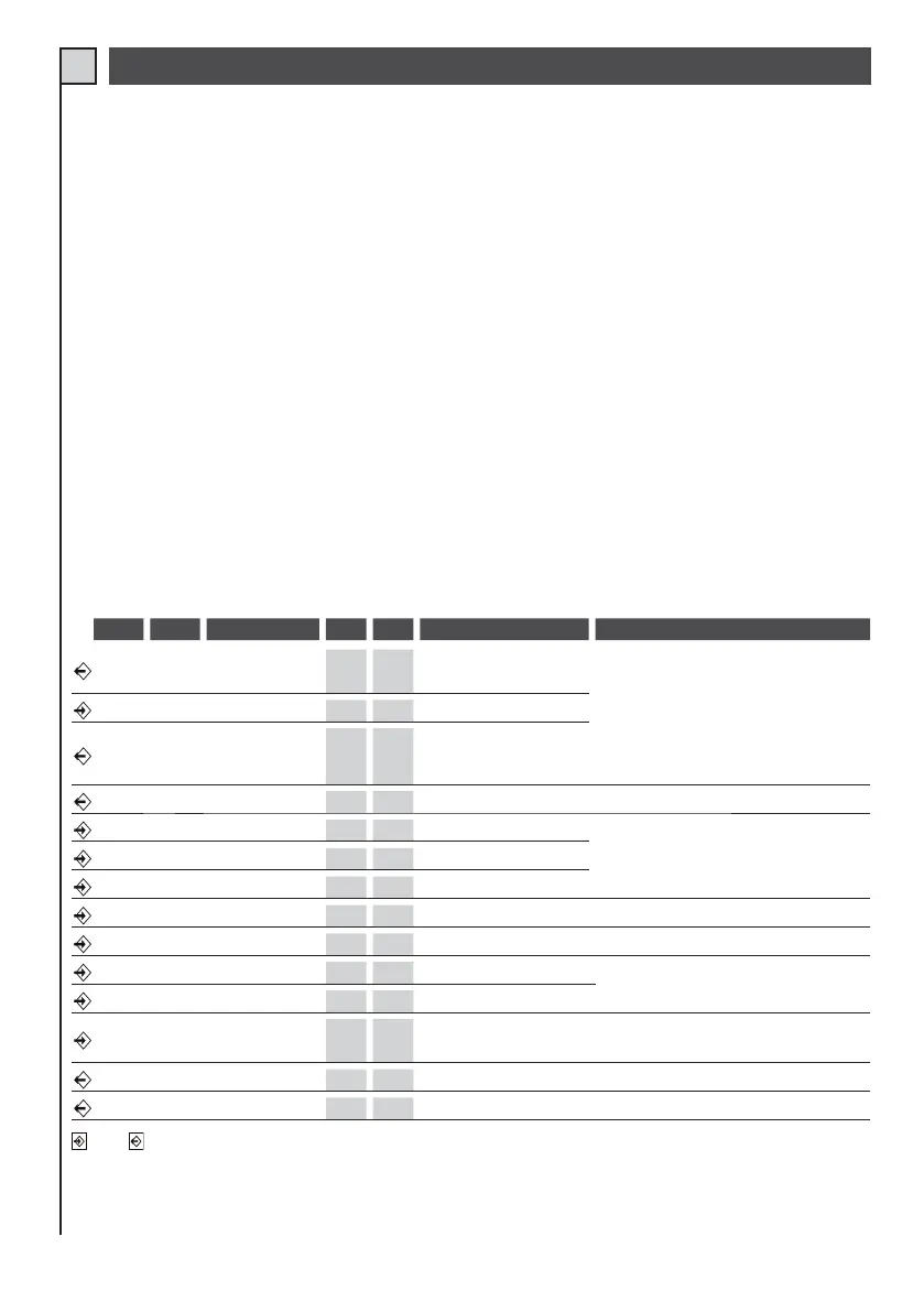
Mor n. Device V I max Function Notes
12
Transformer
(primary)
230V 0,5A
Power supply
Connect this output to the primary of the transformer supplied
35Line
230V 1A
Control unit power supply
Connect to 230Vac line. See electrical connections.
67
Flashing light or
lamp
230V 0,5A
Movement indicator
During the manoeuvres with control unit powered
by battery only, the flashing frequency is reduced.
Lit during manoeuvre. Activation can be set in advance (pre-flashing):
see function dip switch no. 5. Other functions are possible with this output
by combining dip-switches 3 and 4 (see table 3)
89Lamp
12Vcc 1A
Courtesy light
Lit during manoeuvres, and turns off with a delay of approx. 2 minutes.
11 10 , 15 NO/NC Contact Edge on closing (C.M.)
On closing stops the motor and opens completely. See table 2 for
connection types.
12 10 , 15 NC contact. Photocell 1
Inverts travel during closing.
Connect this input to the common if not used.
13 10 , 15 NC contact. Stop
Blocks all functions.
Connect this input to the common if not used.
14 10 , 15 N.O. pushbutton. Step/step
See function dip-switch no.1 and 2 (table 3)
16 17 Auxiliary
24Vcc 1A
Power supply
Permanent for power supply of photocells and external receivers.
18 Rx aerial Sheath
If a receiver is connected to the specific connector, see aerial
specifications as required by the manufacturer.
19 Rx aerial Control unit
20 21
Transformer
(secondary)
22Vca 6,8A
Power supply
Connect this input to the secondary of the transformer supplied (22V).
22 23 CB24
24Vcc 5A
Battery charger (optional)
Provision for connection of battery charger CB24 (optional) and
batteries (optional)
24 25 Motor
24Vcc 5A
Open/close
Input Output
TAB. 1
ELECTRICAL CONNECTIONS
For connections, refer to tables 1 and 2 and figure 15.
In the case of existing systems a general check should be made of the condition of wiring (section, insulation,
contacts) and auxiliary equipment (photocells, receivers, pushbutton panels, key-operated switches etc.).
1) The section of the cables must be calculated on the basis of their length and absorbed current.
2 Do not use a single “multi-pole” type cable in common with other equipment.
3) When very long control cables are used (over 50 metres) decoupling is recommended by means of relays
installed in the vicinity of the control unit.
5) All N.C. contacts associated with the same input must be connected in series.
6) All N.O. contacts associated with the same input must be connected in parallel.
Recommendations for a correct electrical installation:
4) All N.C. inputs. (photocells, safety edges and stop contacts) not used in the control unit must be
shorted with the common.
- For the control unit power supply, the INSERTION OF AN EXTERNAL DISCONNECT SWITCH (not
supplied) is envisaged, which must be independent and sized according to the load.
- The equipment must be installed « PROFESSIONALLY » by personnel with qualifications as
envisaged by current legislation and in compliance with the standards EN 13241-1, EN 12453 and
EN 12445 governing safety of the automation.