GB
Manual Door intercom devices a / b series 20 / 30 / 40 / 50 / 20-0028A/-0028B
Connection
GB
70 www.behnke-online.com
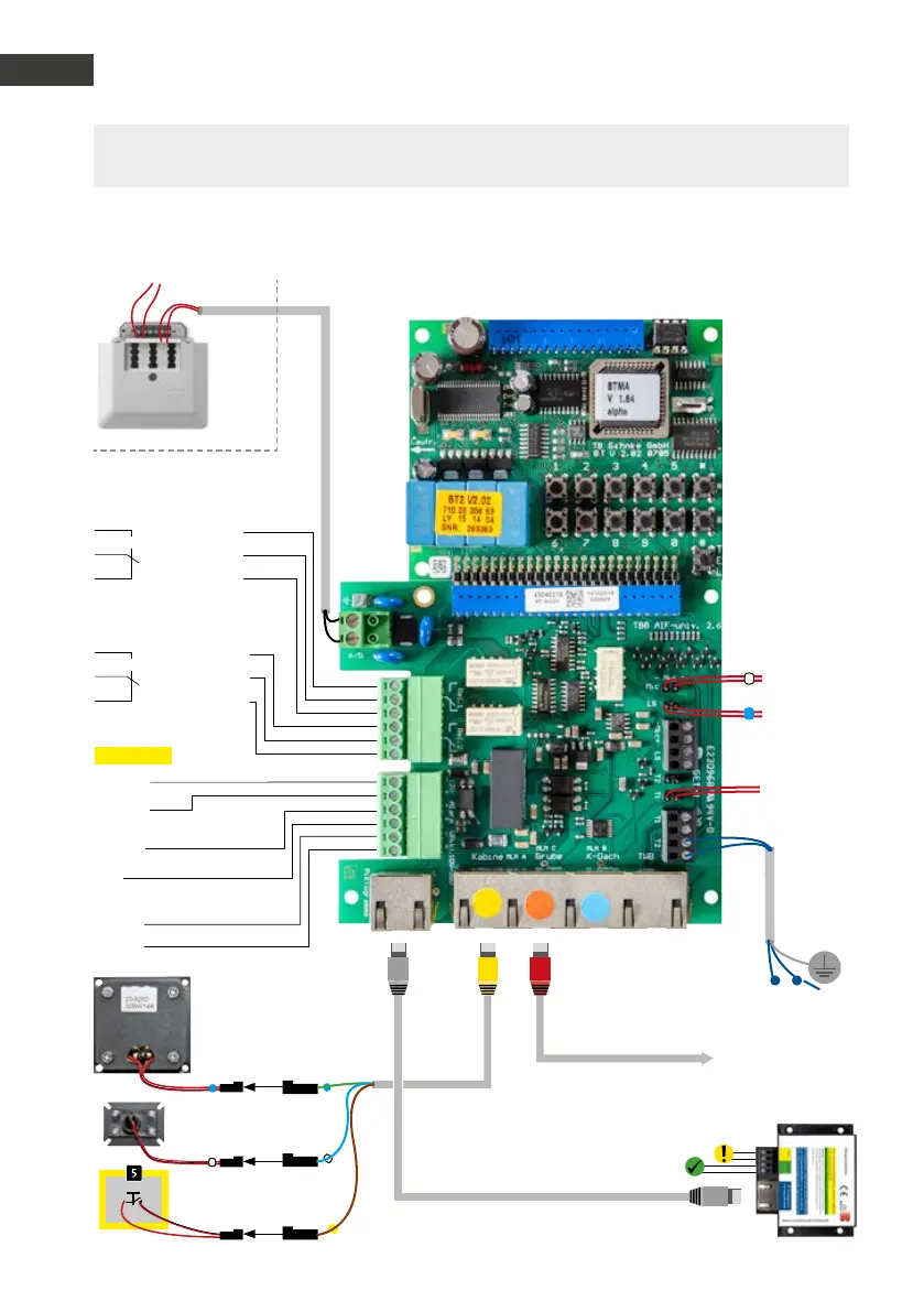
Lift emergency phone 20-0028B (up to firmware version BT MA 1.64, from the second quarter of 2019)
Please note: Please compare your connection boards of the delivered device/rep. kit to the con-
nection boards in the picture. You can find further configuration steps from page 72 onwards.
6 - 24 V =
Alarm input
–
+
Relay 1
Relay switch power: max. 60 VA/24 W:
0,5 A 120 V~ or 1A 24V=
Relay 2
Relay switch power: max. 60 VA
24 W 0.5 A 120 V~ or 1A 24V=
Operating contact
Control contact
Rest contact
Operating contact
Control contact
Rest contact
12 V - 15 V=
Additional
power supply
potential-free voltage
e.g. from a Behnke power supply unit
–
+
Alternative: Front cover
with pictogram 22-9416
To the outside
intercom station
under the cabin 20-9230
Red patch cable
20-9302
Yellow patch cable
20-9309
to the on-site pictograms.
Please note the technical specifications
of the on-site pictograms.
Distance between speakers
and microphone must be
at least 15 cm
Built-in microphone
20-9204
Emergency call button
in the cabin
T
To the button
in the cover
T1
To the speaker
in the cover
To the microphone
in the cover
Alternative to T2*
Screen
Analogue landline connection, analogue extension of a
telephone system or GSM gateway
Pictogram control
10 - 35 V =
–
+
Travelling cable
Grey patch cable
20-9329
Patch cable CAT 5 max. 10m
 Loading...