20
4.4 Trouble in CW transmission
CW transmission is synchronized with CW sending clock.
The CW sending clock is made in IC35, and is fed from CW sending clock input port (pin 2 of IC40)
into the Computer block.
When this clock stops oscillation, CW cannot be transmitted.
The oscillation waveform at TP-3 is fixed at L level within about 15 to 20 µs, while the duration of
H level varies with the position of SPEED slide VR.
Since the monitor sound, CW LED flickering, transceiver transmission/reception selection, and CW
key operation are controlled by the output of IC27, when the CW sending clock is normal and
other functional part is in trouble, see the actions of external control signal output ports (par. 3.2).
4.5 Trouble in CW reception
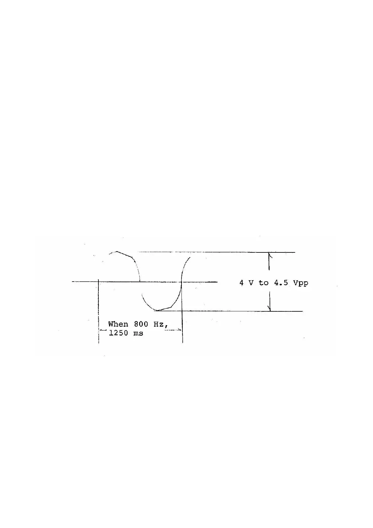
When reception of CW is in trouble, check if signal appears at check points of TP-5, TP-2, TP-4.
While referring to the flow of signal (par. 2.2), check for abnormal action. The TP-5 waveform
should be normally saturated (see below). About 10 % portion is cut as shown below.
If malfunction often occurs due to noise, vary the resistance of R28. When the resistance is incre-
ased, malfunction by noise decreases, whereas the sensitivity drops.
It is also possible to decrease malfunction by noise by adding 0.1 µF to C22 to make a total of
0.3 µF. In this case, however, high speed signals cannot be decoded. Similarly, resistance to noise
is increased when C14 is changed to 22 µF, but the response speed of AGC is slowed down, so
that the resistance to QSB is weakened.