22
5.2 Modulator (AFSK)
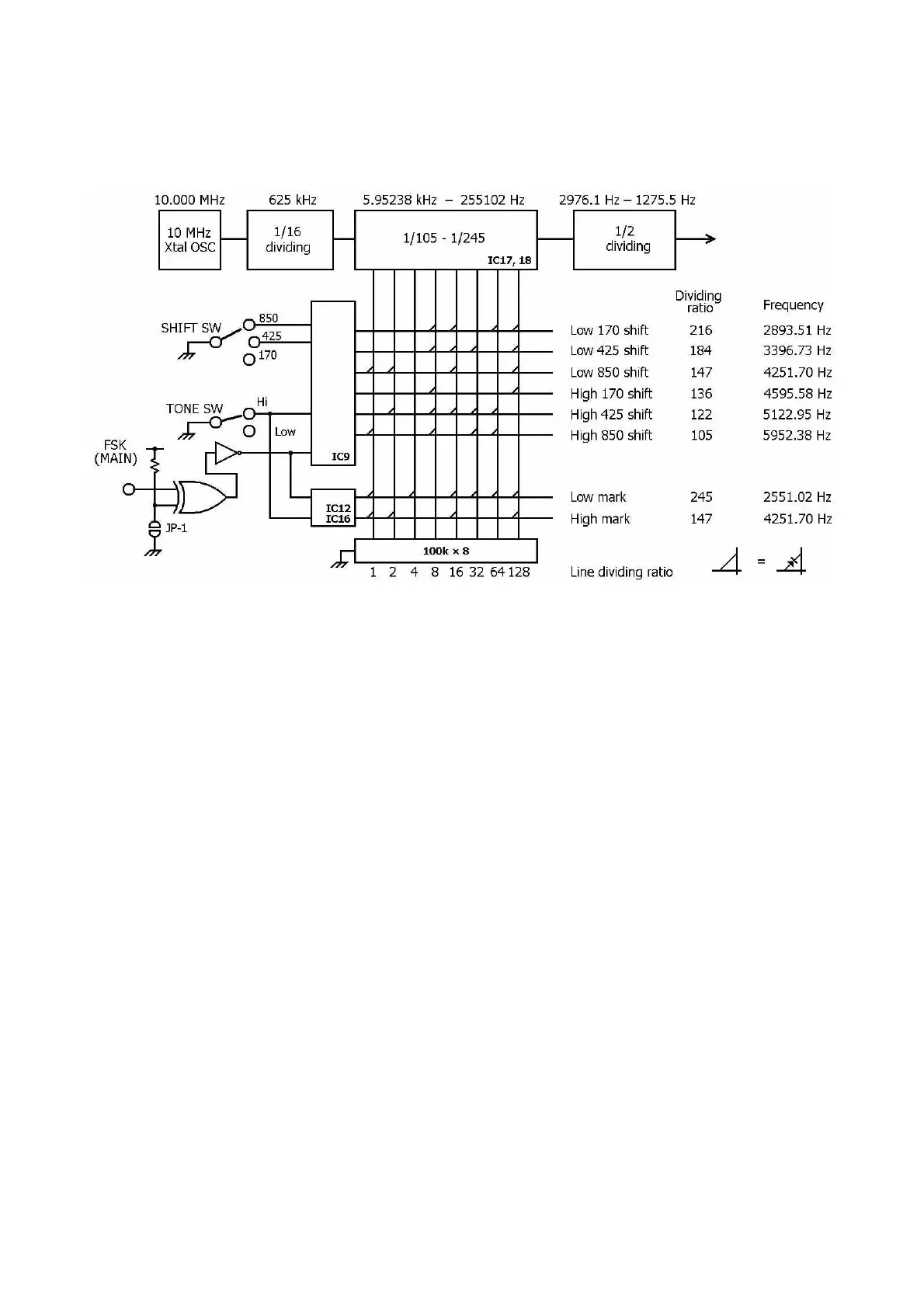
On the basis of the 10 MHz crystal oscillator, necessary frequencies are divided by dividers and
used. The dividing schedule from 10 MHz is as shown below.
The dividing output of IC17, 18 is the total of dividing ratios in all lines where diodes are provided„
Example: Low mark: 1 + 4 + 16 + 32 + 64 + 128 = 245
Input frequency Dividing ratio Output frequency
625 kHz : 245 = 2551.02 Hz
The output divided by the programmable divider is divided again to 1/2, and converted to a neces-
sary frequency of 50 % duty.
One of the converted outputs is passed through audio amplifiers TR3, TR4 to become a monitor
sound output, while the other output runs through the AFSK gain VR and enters the LPF to be cor-
rected in waveform, and becomes an AFSK output.
The AFSK Output can be checked on the TP-9.
5.3 Baud rate clock unit
On the basis of the 10 MHz crystal oscillator in the modulator and the 625 kHz signal being divided
to 1/16, signals are divided to necessary frequency to be delivered.
The dividing schedule from 625 kHz is as shown below: