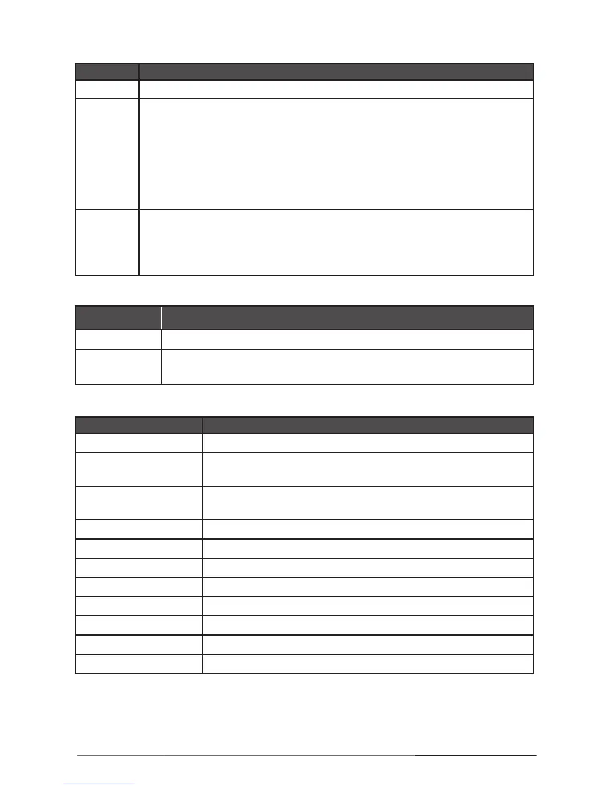
1.1 Operation modes:
MODE Indication
Normal • The green LED next to the ‘power Supply 230V AC’ will be illuminated.
Fire
• The integrated red status FIRE LED and a zone identication LED will
ash together on receipt of a FIRE condition and become steady after the
SILENCE ALARM button is pressed.
• An internal buzzer will operate until silenced with SILENCE BUZZER
button.
• The external sounders will operate.
• The FIRE relay on the main board will energize.
Fault
• The yellow GENERAL FAULT LED will always illuminate together with
an external or internal identication LED.
• An internal buzzer will sound.
• The FAULT relay on the main will de-energize.
1.2 LED indication for the zones status:
ZONE LED Indication
Red • Fire alarm in the zone.
Yellow
• Zone fault - open or short circuit. Detector head removed.
• Zone test - the LED is blinking during the test procedure.
1.3 LED indication for the technical faults:
FAULT Fault description
○ µP Processor break down.
○ Sounder 1
Sounder Circuit One fault - open or short circuit, reverse
connected sounder, or bad sounder parameters.
○ Sounder 2
Sounder Circuit Two fault - open or short circuit, reverse
connected sounder, or bad sounder parameters.
○ +24V DC Overload Overload of “+24” VDC power supply.
○ +24V DC Failed Absence of “+24” VDC power supply.
○ Battery Low Low battery condition.
○ Battery Lost Battery loss.
○ AC Mains Supply loss.
○ Charger Battery charger fault.
○ AUX Auxiliary supply fault.
○ Earth Short circuit to earth.
Battery Low, Battery Lost and Charger LEDs are lighting up together in case of
overload of the battery charger output.