5
Fire Control Panel MAG8 - Installation and Operation Manual
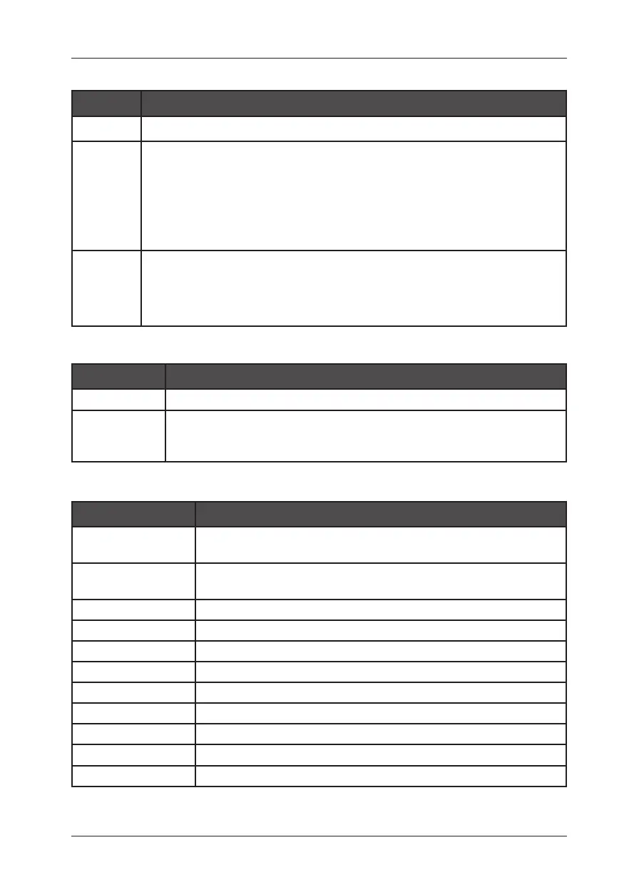
1.1 MAG8 Operation Modes:
MODE Indication
Normal • Only the “POWER SUPPLY 230V” green LED is illuminated.
Fire
• The “FIRE” red LED and the zone red LED will ash together on receipt
of a FIRE condition and become steady after the “SILENCE ALARM”
button is pressed.
• An internal buzzer will operate until silenced.
• The external sounders will operate.
• The FIRE relay will energize.
Fault
• The “GENERAL FAULT” yellow LED will illuminate together with a zone
yellow LED or any of the FAULTS LED.
• An internal buzzer will sound.
• The FAULT relay will de-energize.
1.2 LED indication for the status of the zones (1-8):
ZONE LED Indication
Red Fire in the zone.
Yellow
Technical fault in the zone - open or short circuit; detector removed
from its base.
Zone test - the LED is ashing during the test procedure.
1.3 LED indication for the technical faults in the system:
FAULT Fault description
Sounder 1
Sounder Circuit One fault - open or short circuit, reverse
connected sounder, or bad sounder parameters.
Sounder 2
Sounder Circuit Two fault - open or short circuit, reverse
connected sounder, or bad sounder parameters.
+24V DC Overload Overload of “+24” VDC power supply.
+24V DC Failed Absence of “+24” VDC power supply.
Battery Low Low battery condition; broken battery (high battery resistance).
Battery Lost Battery loss.
AC Mains Supply loss.
Charger Battery charger fault.
AUX Auxiliary supply fault.
Earth Short circuit to earth.
Repeater Repeater fault or missing.