Safety Instructions
*Self-regulating gain.
LIGHTNING PROTECTION
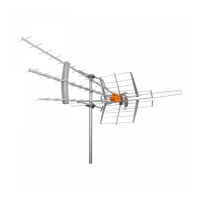
TECHNICAL SPECIFICATIONS
WARNINGS
• If installed outdoors, be sure the antenna system
is grounded so as to provide protection against
voltage surges and built-up static charges.
Section 810 of the National Electrical Code ANSI/
NFPA70, or CSA C22.1 sections 10, 16, and 54, of
the Canadian Electrical Code, provide information
with respect to proper grounding of the mast nd
supporting structure, grounding of the antenna
lead-in wire to an antenna discharge unit, size
of grounding conductors, location of antenna-
discharge unit, connection to grounding electrodes,
and requirements for the grounding electrode (see
figure and instructions).
• Mount the lightning arrestor or 75 ohm coaxial
grounding block as close as possible to where the
75 ohm coaxial cable down lead enters the house.
• The ground wires for both the mast and the down
lead should be copper or aluminium wire, number
eight (8) or larger.
• The down lead wire from the antenna to the
lightning arrestor and the mast ground wire should
be secured to the house, spaced from four (4) to six
(6) feet apart.
• In the case of a “ground up” antenna installation
it may not be necessary to ground the mast if
the mast extends four or more feet in the earth.
Consult a TV serviceman for the proper depth in
your location.
• To prevent fire or shock hazard, do not expose the
included power supply to rain or moisture.
• Installation of off-air antennas near power lines is
dangerous. For your safety, follow the installation
instructions.
• Any alteration or modification to the product or
usage not in accordance with product instructions
voids the warranty.
Antenna L ead
in Wire
Example of antenna grounding as per
National Electrical Code, ANSI/NFPA 70
NEC - National Electrical Code
Ground
clamp
Electric Service
Equipment
Ground clamps
Power service Grounding Electrode System
(NEC Art 250, Part H)
Antenna Discharge Unit
(NEC Section 810-20)
(May s ubstitute a 7 5 ohm
Coax Grounding Block)
Grounding Conductors
(NEC Section 810-21)
Outputs 5G VERTICAL HORIZONTAL
Frequency 630 - 960 MHz
1.7 - 2.7 GHz
UHF
(Ch.14 - Ch.36)
470 - 608MHz
High VHF / UHF
(Ch.7 - Ch.13) / (Ch.14 - Ch.36)
174-216 MHz / 470-608 MHz
Gain 0dBi 32dBi* 23dBi*/dBi32*
Crosspolar rejection >13dB
Power 150mA @ 5V DC
Dimensions 14” x 14” x 4” (w/o pole mount)
Temp. Range -5°C - 45°C
IP Rating IP53