Telink TLSR8232 BLE SDK Developer Handbook
AN-19112700-E1 149 Ver.1.0.0
7. Key Scan
Keyscan architecture based on row/column scan is used to detect and process key state
update (press/release). Users can directly use the sample code, or realize the function by
developing his own code.
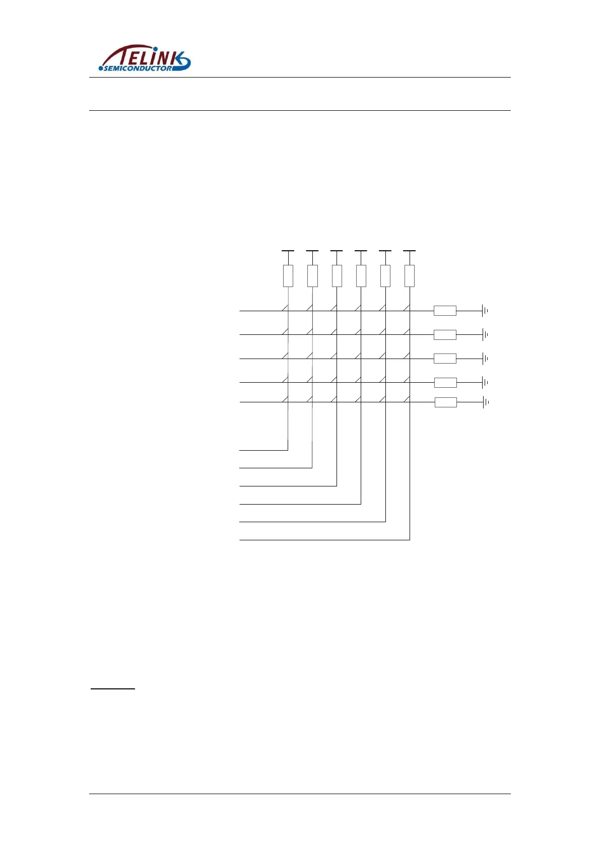
7.1 Key Matrix
Take Telink 5316 BLE remote demo board as an example: It’s a 5*6 matrix and supports
up to 30 buttons. Five drive pins (Row0~Row4) are used to output drive level, while six
scan pins (CoL0~CoL5) serve to scan for button press in current column.
VCCVCC VCC VCC VCC VCC
Drive
Pin
Scan
Pin
Row0
Row1
Row2
Row3
CoL0
CoL1
CoL2
CoL3
CoL4
CoL5
Row4
Figure 7-1 Row/Column Key Matrix
Keyscan related configurations in app_config.h are shown as below:
On Telink demo board, Row0~Row4 pins are PA5, PA4, PA3, PA2, and PA1, while
CoL0~CoL5 pins are PC6, PC5, PC4, PC3, PC2, and PC1.
Define drive pin array and scan pin array:
#define KB_DRIVE_PINS {GPIO_PA5, GPIO_PA4, GPIO_PA3, GPIO_PA2, GPIO_PA1}
#define KB_SCAN_PINS {GPIO_PC6, GPIO_PC5, GPIO_PC4, GPIO_PC3, GPIO_PC2,
GPIO_PC1}
Keyscan adopts analog pull-up/pull-down resistor in TLSR8232 IC: drive pins use 100K
pull-down resistor, and scan pins use 10K pull-up resistor. When no button is pressed,
scan pins act as input GPIOs and read high level due to 10K pull-up resistor. When key
scan starts, drive pins output low level; if low level is detected on a scan pin, it indicates
there’s button pressed in current column (Note: Drive pins are not in float state, if output