LE910C1 Hardware User Guide
1VV0301298 Rev. 1.08 - 2017-11-14
Reproduction forbidden without written authorization by Telit Communications S.p.A. - All Rights Reserved
Telit Confidential Information, provided under NDA Page
21 of 119
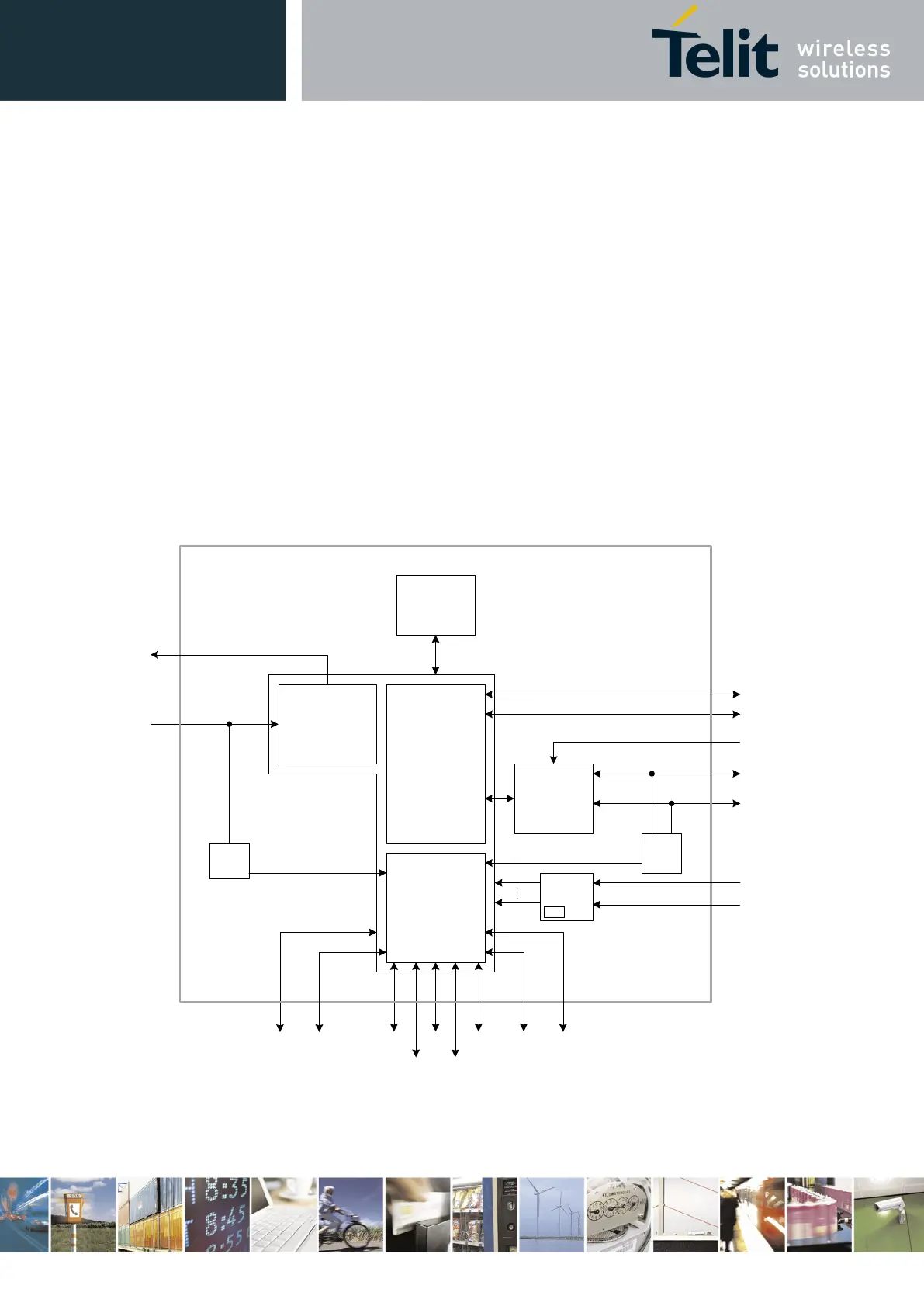
2.4. Block Diagram
Figure 1 shows an overview of the internal architecture of the LE910C1 module.
It includes the following sub-functions:
• Application processor, Modem subsystem and Location processing with their external
interfaces. These three functions are contained in a single SOC.
• RF front end, including antenna diagnosis circuitry
• Analog Audio codec for attaching external speaker amplifier and microphone
• Rich IO interfaces. Depending on which LE910C1 software features are enabled, some of
its interfaces that are exported due to multiplexing may be used internally and thus may
not be usable by the application.
• PMIC with the RTC function inside
Figure 1: LE910C1 Block Diagram
ANT
DIAG
MEMORIES
RF
FRONTEND
GNSS Antennna
GPIO
Cellular antenna 1
Cellular antenna
2
PCM In/out
SIM
GNSS_Sync
APPLICATION
PROCESSOR
MODEM
LOCATION
HSICI2C
ANT
DIAG
USB2.0SGMIISPI
UART
JTAG 2xSDIO
PMIC
VBATT
ADC
VBATT_PA
RTC