9
Temco VF36RN/RNH/RP
78586
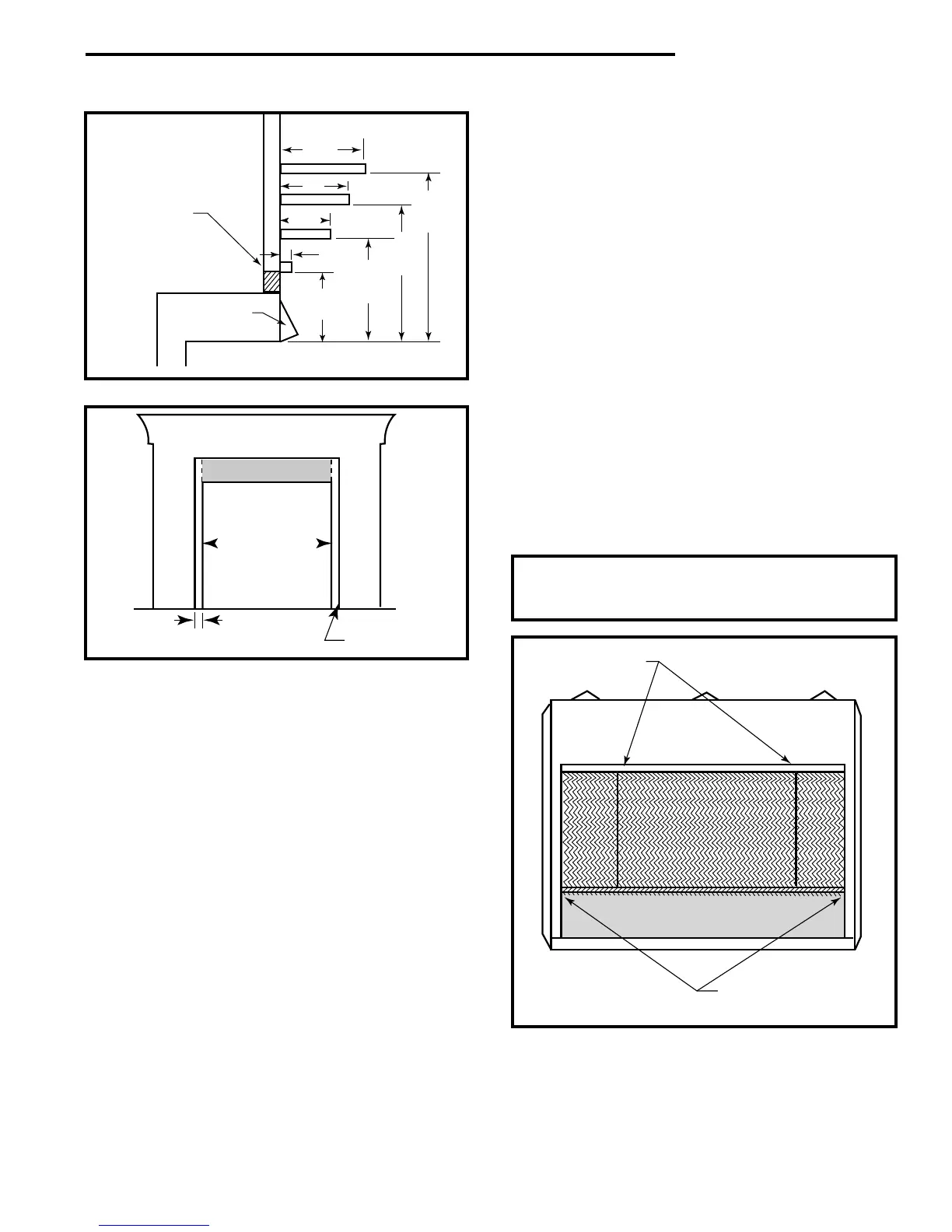
10"
8"
6"
1"
9"
Min.
12"
Min.
18"
Min.
22"
Min.
Heat Resistant
Material
Universal
Canopy
T107
Fig. 6b Minimum clearances with universal canopy.
Fireplace
Opening
Combustible Mantel
Noncombustible
Facing
Mantel Leg
Mantel Leg
2” Min.
Clearance
Max. Projection
7”
T108
Fig. 7 Side clearance and projection.
This list of specific instructions will help you make
certain that every installation operation is done
correctly. Complete the installation steps in the
sequence shown.
LOCAL BUILDING CODES SHOULD BE CONSULTED
IN ALL CASES AS TO THE PARTICULAR REQUIRE-
MENTS CONCERNING THE INSTALLATION OF
FACTORY BUILT VENT FREE FIREPLACES.
Select the location for the fireplace by taking into
consideration the factors previously outlined in the
Planning Ahead section of this manual.
Step 1: Framing the Firebox
The entire fireplace can be elevated above the floor to
achieve a raised hearth effect. This can be done by
adding a small platform to achieve the desired height.
STOP! INSTALL CANOPY AT THIS TIME BY LOOS-
ENING THE SCREWS LOCATED AT THE TOP
FRONT OF THE FIREPLACE. NEXT, SLIDE THE
SLOTTED FLANGE OF THE CANOPY UNDER THE
LOOSENED SCREWS, THEN RETIGHTEN THE
SCREWS TO SECURE THE CANOPY.
Step 2: Install the Firebox
Install the firebox into the framed opening by setting it
directly in front of the opening and sliding it into the
proper position.
Step 3: Level the Firebox
Check the level of the firebox on the top edge of the
fireplace face. Shim if necessary.
Step 4: Secure the Firebox
Secure the fireplace to the framing. The nailing flanges
on the firebox will make securing the firebox to the
frame quick and easy. Use appropriate size nails or
screws to secure the firebox.
Step 5: Removing the Front Screen Panel
To remove the screen panel, first open the control panel
door. Using a 1/4" nut driver, remove the two screws
that secure the screen panel to the front of the fire-
place, (Refer to Figure 8 for the location). Carefully pull
the bottom of the screen panel out toward you, then pull
the panel down until the two pins at the top of the
screen panel clears the holes in the top of the fireplace.
Reverse the above operation to reinstall the screen
panel.
WARNING: The front screen on the fixed screen
models must be installed before the fireplace is
put into operation.
Pins Securing Top of
Screen Panel
Screws Securing Bottom of
Screen Panel
(Control Panel Door is Open)
T145
Fig. 8 To remove screen panel, remove two screws securing
screen, then pull panel down until top pins clear holes in top
of fireplace.