Temposonics
®
E-Series IO-Link
Operation Manual
I 9 I
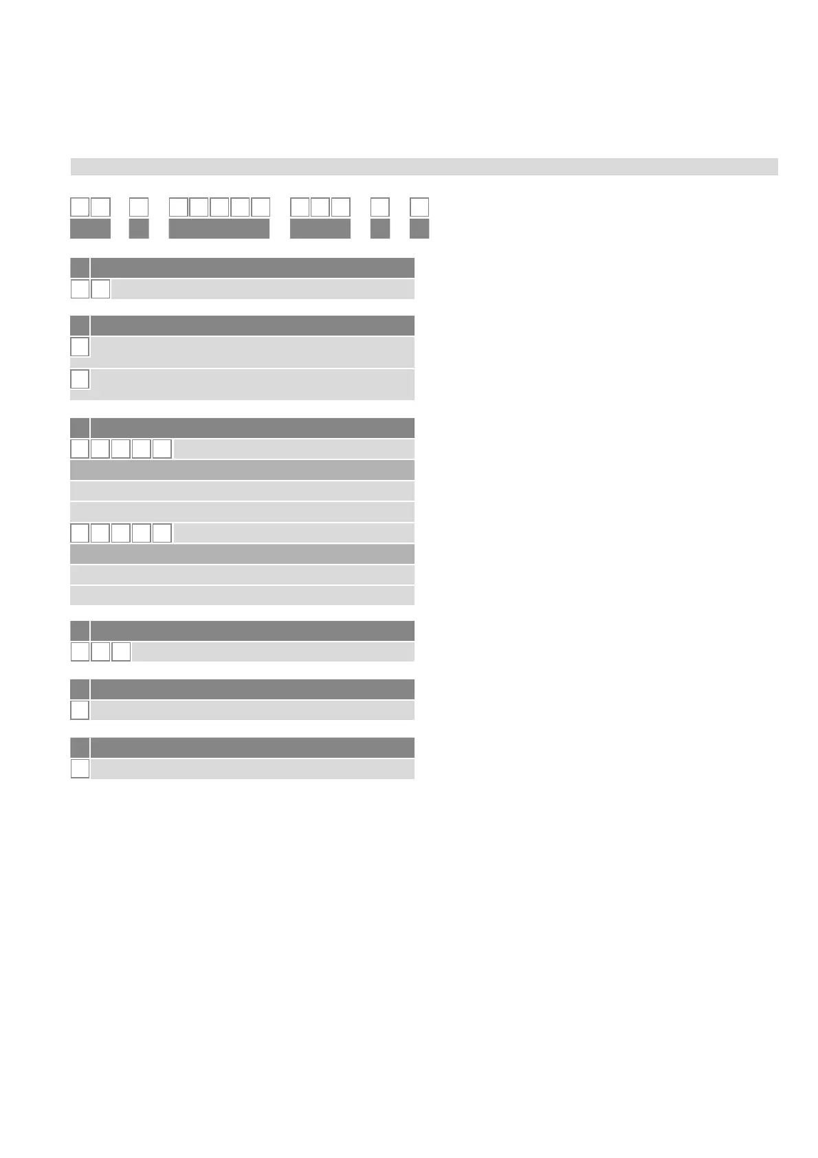
3.5 Order code of Temposonics
®
ER
1 2 3 4 5 6 7 8 9 10 11 12 13
E
R
D 4 4
1
K
ab c d ef
b Design
M
Inside thread M6 at end of rod
(For metric stroke length measurement)
S
Inside thread ¼"-28 UNF at end of rod
(For US customary stroke length measurement)
a Sensor model
E R
Aluminum cylinder with a guided driving rod
d Connection type
D 4 4
M12 (4 pin) male connector
e Operating voltage
1
+24 VDC (±25 %)
f Output
K
IO-Link
*/ Non standard stroke lengths are available; must be encoded in 5 mm / 0.1 in. increments
c Stroke length
X X X X M
0050…1500 mm
Standard stroke length (mm*) Ordering steps
50 … 500 mm 25 mm
500…1500 mm 50 mm
X X X X
U
002.0…060.0 in.
Standard stroke length (in.) Ordering steps
2 … 20 in. 1.0 in.
20 …60 in. 2.0 in.
.


 To Next Page