INSTALLATION INSTRUCTIONS Gas Furnace: (F/G)MAC
440 01 4201 01 11
Specifications subject to change without notice.
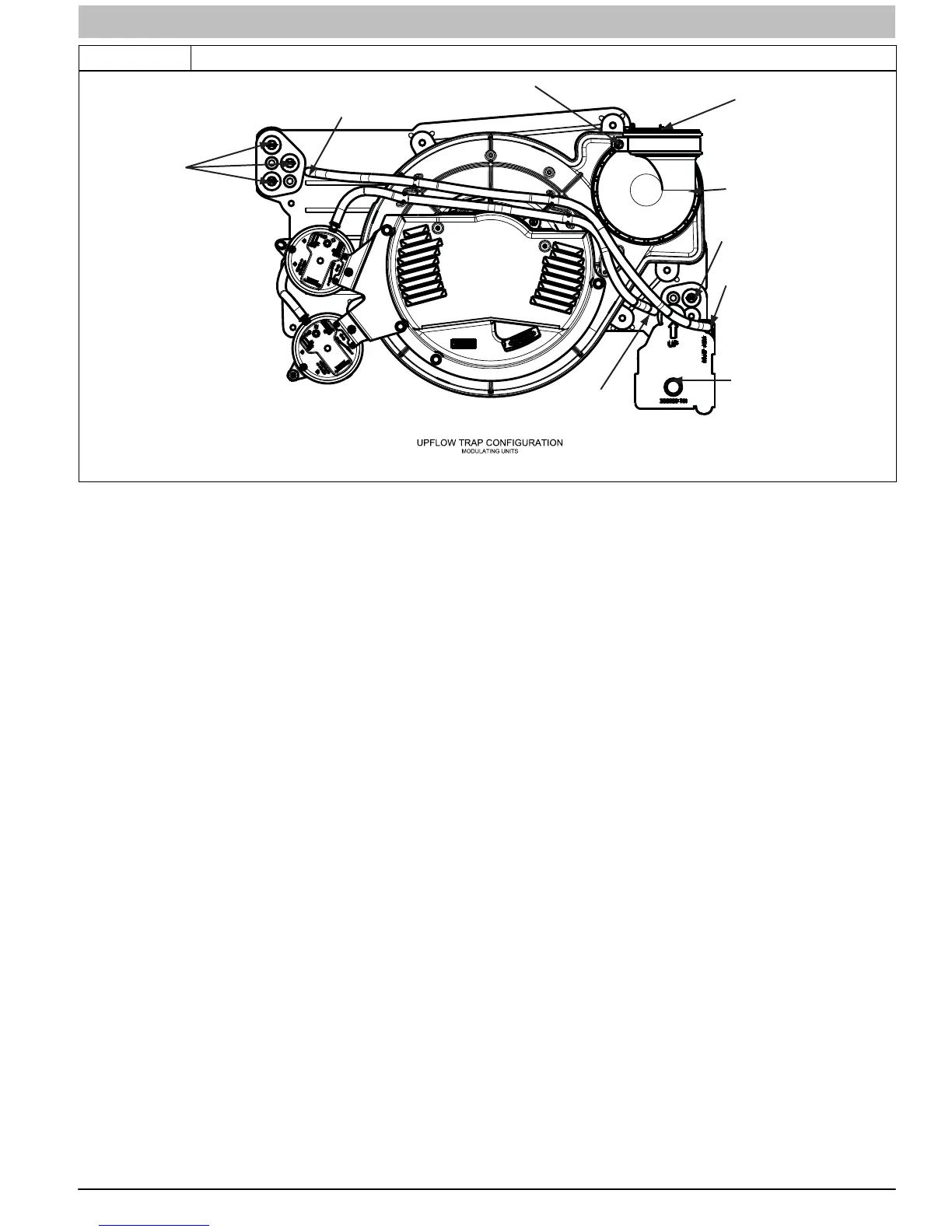
Figure 7 Upflow Trap Configuration
Condensate Trap
Relief Port
Collector Box
Plugs
Pressure Switch
Port
Condensate Trap
Outlet
Condensate Trap
Relief Port
Collector Box
Plug
Vent Elbow
Vent Elbow Clamp
Vent Pipe Clamp
A11306Representative drawing only, some models may vary in appearance.
To Relocate the Condensate Trap:
1. Orient the furnace in the downflow position.
2. Figure 8 shows the condensate trap and tubing before
and after relocation.
3. Refer to the appropriate figure to begin the trap
conversion.
4. Remove the relief tube from the condensate trap.
5. Remove the screw that secures the condensate trap to
the collector box.
6. Remove the trap.
7. Remove the relief tube from of the port on the collector
box. It is not necessary to remove the hose from the
inducer assembly.
8. Remove the pressure switch tube from the port on the
collector box.
9. Remove the pressure switch tube from the stand−offs on
the inducer assembly
10. Loosen the clamp around the inlet of the vent elbow on
the inducer.
11. Remove the middle and bottom plugs from the lower
right side of the collector box and set aside. Do Not
Discard Plugs.
12. Refer to the appropriate figure to begin the trap
conversion.
13. Install the two (2) plugs previous removed from the
collector box in the ports where the condensate trap was
removed.
14. Install the trap over the ports on the lower right side of
the collector box.
15. Secure the trap to the collector box with the screw.
16. Connect the relief tube to the condensate trap to the
relief port of the condensate trap.
17. If necessary, slide the relief tube in the inducer
stand−offs to adjust the position of the tube.
18. Connect the relief tube to the relief port of the
condensate trap.
19. Route the pressure switch tube to the port on the
collector box next to the condensate trap. Trim off any
excess tube to avoid sags or kinks in the tube.
20. Rotate the vent elbow to the desired position and tighten
the clamp 15 in.−lbs.
21. Refer to Condensate Drain section for information how to
install the condensate drain.