INSTALLATION INSTRUCTIONS Gas Furnace: (F/G)MAC
18 440 01 4201 01
Specifications subject to change without notice.
openings using light assistance or a probe can be inserted for
sampling the air stream. The cover attachment shall prevent
leaks.
Connect supply−air duct to flanges on furnace supply−air
outlet. Bend flange upward to 90 with wide duct pliers. (See
Figure 21) The supply−air duct must be connected to ONLY
the furnace supply−outlet−air duct flanges or air conditioning
coil casing (when used). DO NOT cut main furnace casing side
to attach supply air duct, humidifier, or other accessories. All
accessories MUST be connected to duct external to furnace
main casing.
Return Air Connections
!
WARNING
FIRE HAZARD
A failure to follow this warning could cause personal
injury, death and/or property damage.
Never connect return−air ducts to the back of the
furnace. Follow instructions below.
The return−air duct must be connected to bottom, sides (left or
right), or a combination of bottom and side(s) of main furnace
casing as shown in Figure 26, Figure 27 and Figure 28.
Bypass humidifier may be attached into unused return air side
of the furnace casing.
Bottom Return Air Inlet
These furnaces are shipped with bottom closure panel installed
in bottom return−air opening. Remove this panel when bottom
return air is used. This panel may be used as the bottom
closure of an accessory bottom return air box or discarded. To
remove bottom closure panel, perform the following:
1. Tilt or raise furnace and remove four (4) screws holding
bottom plate. (See Figure 18)
2. Remove bottom plate.
3. Remove bottom closure panel.
4. Reinstall bottom plate and screws.
Figure 18 Removing Bottom Closure Panel
L11F004
BOTTOM
PLATE
Side Return Air Inlet
These furnaces are shipped with bottom closure panel installed
in bottom return−air opening. This panel MUST be in place
when only side return air is used.
NOTE: Side return−air openings can be used in UPFLOW and
most HORIZONTAL configurations. Do not use side return−air
openings in DOWNFLOW configuration. (See Figure 26,
Figure 27 and Figure 28)
Leveling Legs (If Desired)
In upflow position with side return inlet(s), leveling legs may be
used. (See Figure 19) Install field−supplied, 5/16 x 1−1/2 in. (8
x 38 mm) (max) corrosion−resistant machine bolts, washers
and nuts.
Figure 19 Leveling Legs
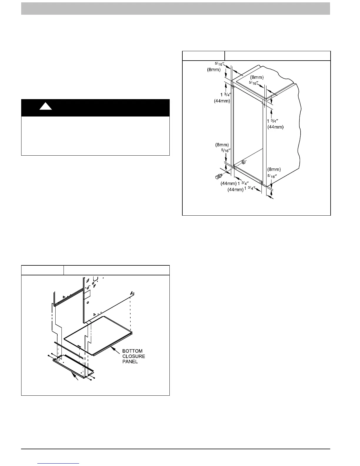
A89014
NOTE: Bottom closure must be used when leveling legs are
used. It may be necessary to remove and reinstall bottom
closure panel to install leveling legs. To remove bottom closure
panel, see Step 1 in Bottom Return Air Inlet section.
To install leveling legs:
1. Position furnace on its back. Locate and drill a hole in
each bottom corner of furnace.
2. For each leg, install nut on bolt and then install bolt with
nut in hole. (Install flat washer if desired.)
3. Install another nut on other side of furnace base. (Install
flat washer if desired.)
4. Adjust outside nut to provide desired height, and tighten
inside nut to secure arrangement.
5. Reinstall bottom closure panel if removed.
DOWNFLOW INSTALLATION
NOTE: The furnace must be pitched forward as shown in
Figure 17 for proper condensate drainage.
Supply Air Connections
NOTE: For downflow applications, this furnace is approved for
use on combustible flooring when any one of the following
three accessories are used (see Specification sheets for list of
approved accessories):
• Special Base − NAHA01101SB
• Cased Coil Assembly − END4X, ENW4X
1. Determine application being installed from Table 5.
2. Construct hole in floor per Table 5 and Figure 20.
3. Construct plenum to dimensions specified in Table 5
and Figure 20.
4. Install as shown in Figure 22. If Coil Assembly Part is
used, install as shown in Figure 23 .