INSTALLATION INSTRUCTIONS Gas Furnace: (F/G)MAC
440 01 4201 01 19
Specifications subject to change without notice.
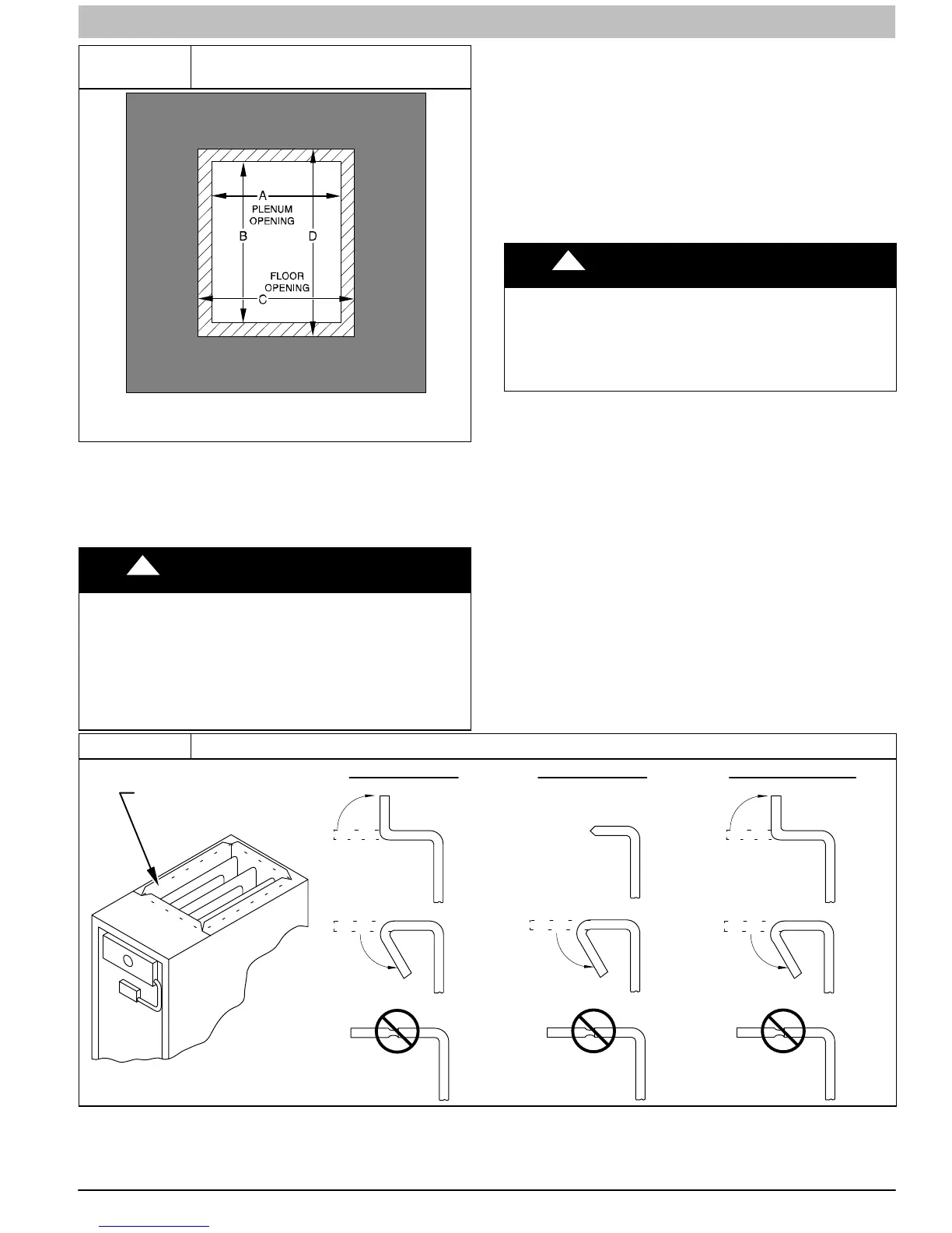
Figure 20
Floor and Plenum Opening
Dimensions
A96283
NOTE: It is recommended that the perforated supply−air duct
flanges be completely removed from furnace when installing
the furnace on a factory−supplied cased coil. To remove the
supply−air duct flange, use wide duct pliers or hand seamers to
bend flange back and forth until it breaks off. Be careful of
sharp edges. (See Figure 21)
!
CAUTION
CUT HAZARD
Failure to follow this caution may result in personal
injury.
Sheet metal parts may have sharp edges or burrs. Use
care and wear appropriate protective clothing, safety
glasses and gloves when handling parts, and servicing
furnaces.
Connect supply−air duct to supply−air outlet on furnace. Bend
flange inward past 90 with wide duct pliers (See Table 1
Figure 21) The supply−air duct must be connected to ONLY
the furnace supply outlet or air conditioning coil casing (when
used). When installed on combustible material, supply−air duct
must be connected to ONLY the factory−approved accessory
subbase, or a factory−approved air conditioning coil casing. DO
NOT cut main furnace casing to attach supply side air duct,
humidifier, or other accessories. All accessories MUST be
connected to duct external to furnace casing.
Return Air Connections
!
WARNING
FIRE HAZARD
A failure to follow this warning could cause personal
injury, death and/or property damage.
Never connect return−air ducts to the back of the
furnace. Follow instructions below.
The return−air duct must be connected to return−air opening
(bottom inlet) as shown in Figure 26. DO NOT cut into casing
sides (left or right). Bypass humidifier connections should be
made at ductwork or coil casing sides exterior to furnace. (See
Figure 26)
Bottom Return Air Inlet
These furnaces are shipped with bottom closure panel installed
in bottom return−air opening. Remove and discard this panel
when bottom return air is used in downflow applications. To
remove bottom closure panel, perform the following:
1. Tilt or raise furnace and remove four (4) screws holding
bottom plate panel. (See Figure 18)
2. Remove bottom plate.
3. Remove bottom closure panel.
4. Reinstall bottom plate and screws.
Figure 21 Duct Flanges
UPFLOW DOWNFLOW HORIZONTAL
YES
NO
NO
YES
YES
YES
NO
120
MIN
YES
120
MIN
YES
120
MIN
90 90
PERFORATED
DISCHARGE DUCT
FL ANGE
A10493