INSTALLATION INSTRUCTIONS Gas Furnace: (F/G)MAC
6 440 01 4201 01
Specifications subject to change without notice.
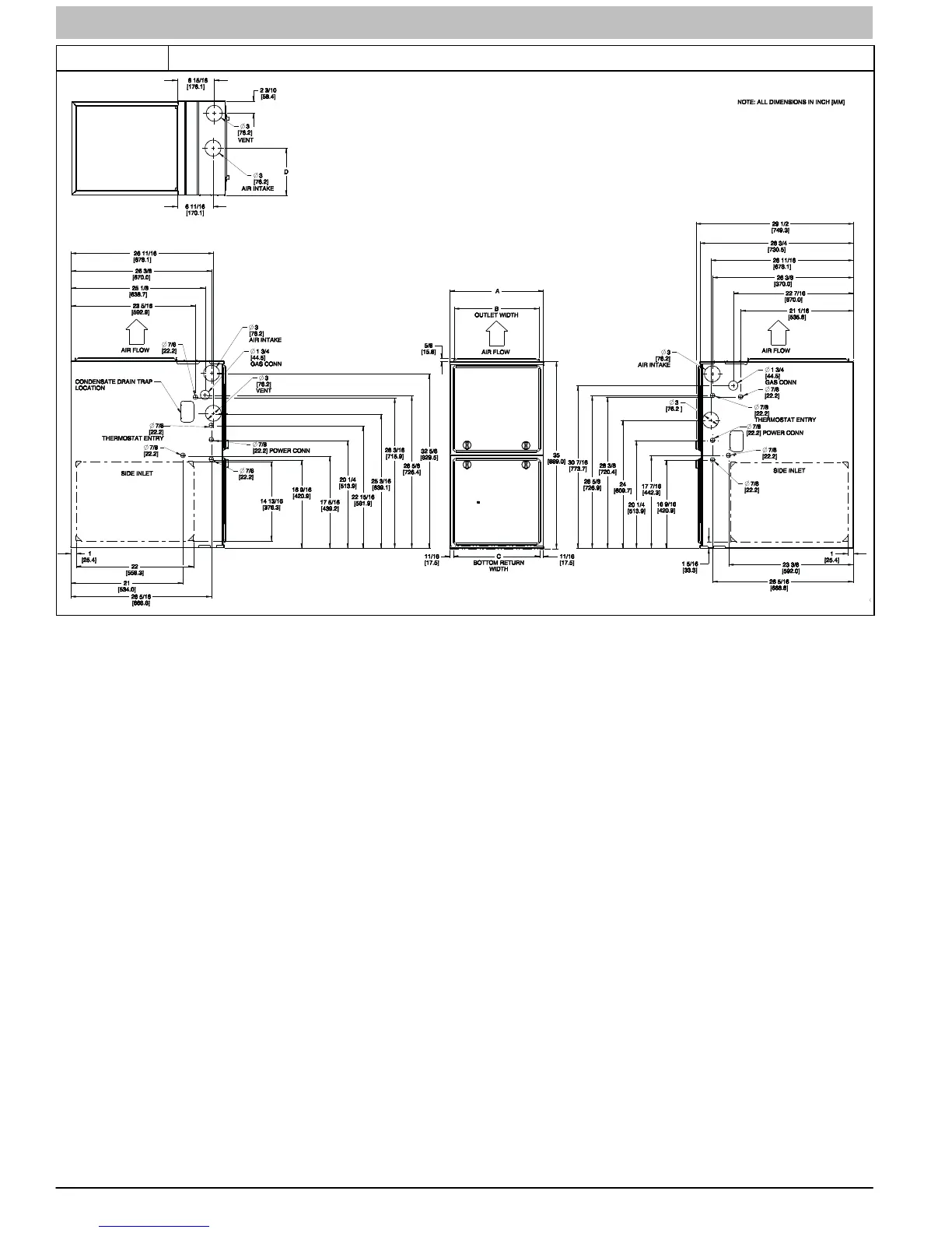
Figure 2 Dimensions
(F/G9MAC)
FURNACE SIZE
A B C D
SHIP WT.
LB (KG)
CABINET WIDTH OUTLET WIDTH
BOTTOM
INLET WIDTH
AIR INTAKE
60,000 17−1/2 (445) 15−7/8 (403) 16 (406) 8 3/4 (222) 154 (69)
80,000 17−1/2 (445) 15−7/8 (403) 16 (406) 8 3/4 (222) 164 (73)
100,000 21 (533) 19−3/8 (492) 19−1/2 (495) 10 1/2 (267) 179 (80)
120,000 24−1/2 (622) 22−7/8 (581) 23 (584) 12 1/4 (311) 203 (91)
NOTE: Doors may vary by model.
a. For 800 CFM 16−in. (406 mm) round or 14 ½ x 12−in. (368 x 305 mm) rectangle.
b. For 1200 CFM 20−in. (508mm round of 14 ½ x 19 ½−in. (368 x 495 mm) rectangle.
c. For 1600 CFM 22−in. (559 mm) round or 14 ½ x 22 1/16−in. (368 x 560 mm) rectangle.
d. For airflow requirements above 1800 CFM, see Air Delivery table in Installation Instructions for specific use of single side
inlets. The use of both side inlets, a combination of 1 side and the bottom, or the bottom only return air openings may be
required for airflow requirements above 1800 CFM at 0.5 in. w.c. ESP