INSTALLATION INSTRUCTIONS Gas Furnace: (F/G)MAC
16 440 01 4201 01
Specifications subject to change without notice.
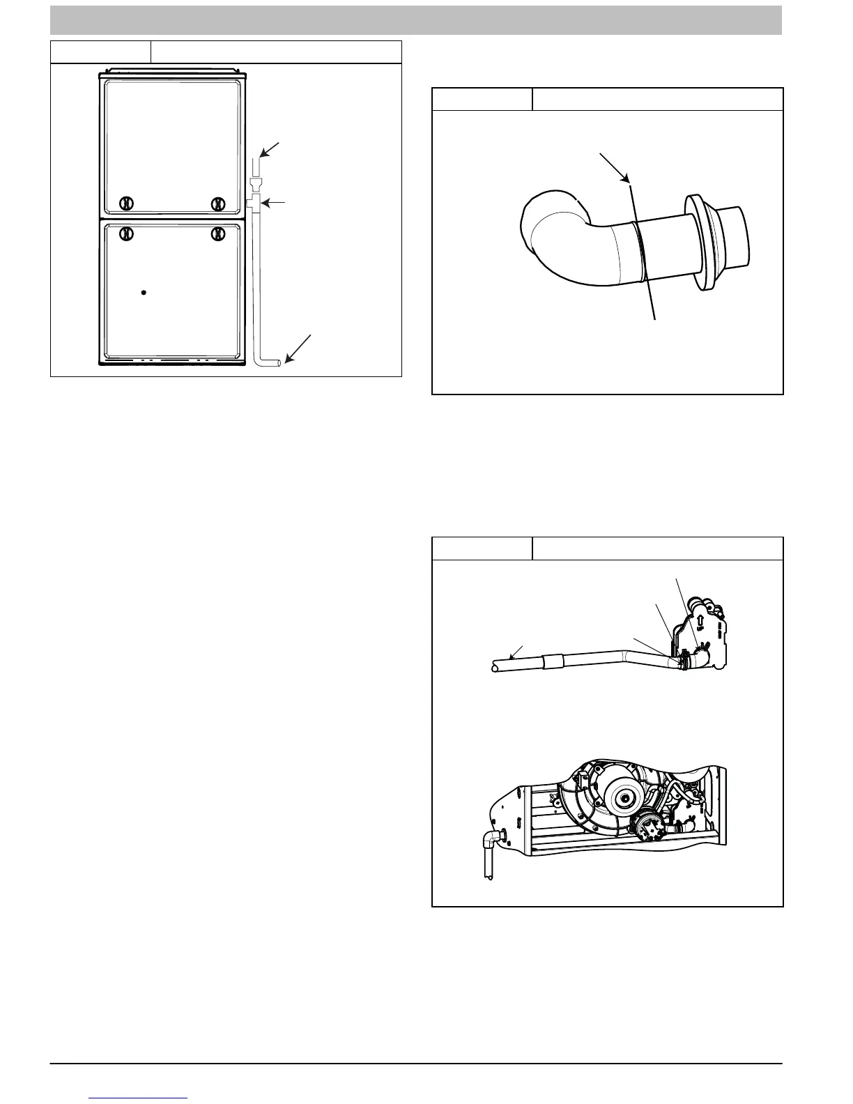
Figure 12 Example of Field Drain Attachment
A11276
OPEN STAND
PIPE FOR
A/C OR
HUMIDIFIER
DRAIN
TEE
TO OPEN
DRAIN
For Right Side Condensate Drain:
1. Remove the 7/8−in. knock−out from the right side of the
casing. (See Figure 15)
2. Remove the pre−formed drain tube and two spring
clamps from the loose parts bag.
3. Slide a spring clamp 1−in. down the plain end of the
drain tube.
4. From inside the casing, insert the formed grommet end
of the tube through the 7/8−in. knockout in the casing.
5. Pull the tube through the casing from the outside until it is
seated in the knockout
6. Attach the plain end of the drain tube to the outlet stub
on the drain trap. Secure the drain tube to the trap with
the spring clamp.
7. Slide a spring clamp over the open end of the drain tube
outside the casing.
8. Open the spring clamp and connect a field−supplied
1/2−in. CPVC street elbow to the open end of the drain
tube.
9. Connect additional 1/2−in. CPVC piping to a condensate
pump approved for use with acidic furnace condensate
or to a code−approved drain.
For Left Side Condensate Drain Connection:
1. For left side condensate drainage, the drain line is routed
from the condensate trap, behind the inducer and out
through the left side of the casing. A pre-formed “Z” pipe
is provided in the loose parts bag shipped with the
furnace. The “Z” pipe is long enough to extend out of the
casing on the 14 3/16-in. (360 mm) wide furnace. Larger
casings will require a field supplied CPVC pipe and to
extend the drain line out of the furnace.
2. The “Z” pipe is connected to the condensate trap by
modifying the formed rubber drain tube. Connect the
drain line as shown below:
3. Remove the knock−out from the left side of the casing.
(See Figure 15)
4. Install the grommet for the 1/2−in. CPVC drain line in the
7/8−in. knockout in the casing.
5. Remove the pre−formed drain tube, the offset 1/2−in.
CPVC pipe and two spring clamps from the loose parts
bag.
6. Remove the formed grommet on the tube by cutting the
tube along the vertical line located about 1−in. away from
the formed grommet. (See Figure 13)
Figure 13 Modify Drain Tube
A11388
RIGHT SIDE DRAIN ELBOW
Cut and remove formed end of
drain tube for left side and horizontal
drain connection
7. Slide a spring clamp 1−in. down the plain end of the
drain tube
8. With the bend in the tube oriented horizontally and plain
end of the tube pointing away from you, insert the 1/2−in
CPVC pipe into the other end of the drain tube. Rotate
the tube so the offset in the tube points away from you.
Slide a spring clamp over the open end of the 1/2−in.
CPVC tube and secure the cut end of drain tube to the
pipe. (See Figure 14)
Figure 14 Drain Trap Connection and Routing
A11344
LEFT SIDE DRAIN ROUTED BEHIND INDUCER
TRAP, DRAIN ELBOW WITH DISCHARGE PIPE
Attach tube to condensate trap
Cut formed end o
condensate drain tube
Connect short end
of “Z” pipe to modied
drain tube
Field supplied 1/2” CPVC
coupling & drain extension
17 1/2“, 21” and 24 1/2” casing
Field supplied 1/2”
CPVC to drain
Casing grommet from
loose parts bag
Modied drain tube connect to
condensate trap and “Z” pipe
Field-supplied 1/2” CPVC coupling & drain
pipe 17 1/2“, 21” and 24 1/2” casings
9. Prime the bare end of the pipe with CPVC primer.
10. Route the offset pipe behind the inducer assembly and
through the grommet in the casing, if the “Z” pipe is long
enough. If the “Z” pipe is not long enough, continue with
installation.
11. Attach the plain end of the drain tube to the outlet stub
on the drain trap. Secure the drain tube to the trap with
the spring clamp.