INSTALLATION INSTRUCTIONS Gas Furnace: (F/G)MAC
26 440 01 4201 01
Specifications subject to change without notice.
Table 8 Maximum Capacity of Pipe
NOMINAL
IRON PIPE
SIZE
IN. (MM)
INTERNAL
DIA.
IN. (MM)
LENGTH OF PIPE − FT (M)
10
(3.0)
20
(6.0)
30
(9.1)
40
(12.1)
50
(15.2
)
1/2 (13)
0.622
(158)
175 120 97 82 73
3/4 (19)
0.824
(20.9)
360 250 200 170 151
1 ( 25)
1.049
(26.6)
680 465 375 320 285
1‐1/4 (32)
1.380
(35.0)
140
0
950 770 660 580
1‐1/2 (39)
1.610
(40.9)
210
0
146
0
1180 990 900
* Cubic ft of gas per hr for gas pressures of 0.5 psig (14-In. W.C.) or less and
a pressure drop of 0.5-In. W.C. (based on a 0.60 specific gravity gas). Ref: Table 8
above, and 6.2 of NFPA54/ANSI Z223.1-2009.
An accessible manual equipment shutoff valve MUST be
installed external to furnace casing and within 6 ft. (1.8 M) of
furnace.
Install a sediment trap in riser leading to furnace as shown in
Figure 31. Connect a capped nipple into lower end of tee.
Capped nipple should extend below level of furnace gas
controls. Place a ground joint union between furnace gas
control valve and exterior manual equipment gas shutoff valve.
Figure 31 Typical Gas Pipe Arrangement
L10F030
A 1/8−in. (3 mm) NPT plugged tapping, accessible for test
gauge connection, MUST be installed immediately upstream of
gas supply connection to furnace and downstream of manual
equipment shutoff valve.
Piping should be pressure and leak tested in accordance with
the current addition of the NFGC in the United States, local,
and national plumbing and gas codes before the furnace has
been connected. Refer to current edition of NSCNGPIC in
Canada. After all connections have been made, purge lines
and check for leakage at furnace prior to operating furnace.
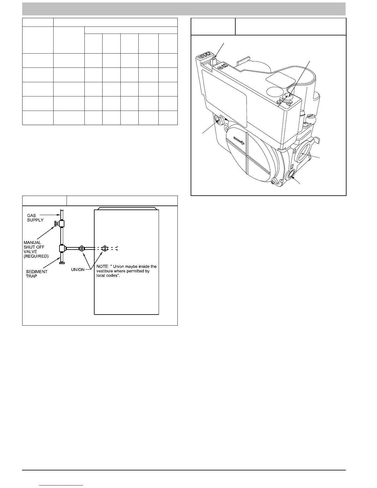
NOTE: The furnace gas control valve inlet pressure tap
connection is suitable to use as test gauge connection
providing test pressure DOES NOT exceed maximum 0.5 psig
(14−in. w.c.) stated on gas control valve. (See Figure 32)
Figure 32
Redundant Automatic Control
Valve (Modulating)
ON/OFF Switch
1/2” NPT Outlet
Manifold
Pressure Tap
Inlet
Pressure Tap
Min/Max Heat Adust
(Under Cap)
GAS FLOW
MODULATING
Turn screw 1 click per
second to adjust rate.
Clockwise to increase
rate, counter clockwise
to decrease rate.
A10496
If pressure exceeds 0.5 psig (14−in. w.c.), gas supply pipe must
be disconnected from furnace and capped before and during
supply pipe pressure test. If test pressure is equal to or less
than 0.5 psig (14−in. w.c.), turn off electric shutoff switch
located on furnace gas control valve and accessible manual
equipment shutoff valve before and during supply pipe
pressure test. After all connections have been made, purge
lines and check for leakage at furnace prior to operating
furnace.
The gas supply pressure shall be within the maximum and
minimum inlet supply pressures marked on the rating plate with
the furnace burners ON and OFF.
Some installations require gas entry on right side of furnace (as
viewed in upflow). (See Figure 33)
Gas Pipe Grommet
For direct vent (2-pipe) applications, the knockout for the gas
pipe must be sealed to prevent air leakage. Remove the
knockout, install the grommet in the knockout, then insert the
gas pipe. The grommet is included in the loose parts bag. (See
Figure 33)