INSTALLATION INSTRUCTIONS Gas Furnace: (F/G)MAC
34 440 01 4201 01
Specifications subject to change without notice.
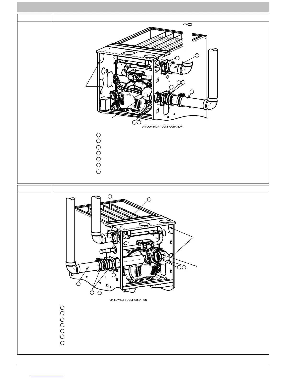
Figure 41 Upflow Right Vent
Attach vent pipe adapter with gasket to furnace casing.
Align notches in rubber coupling over standoffs on adapter. Slide clamps over the coupling.
Slide vent pipe through adapter and coupling into vent elbow.
Insert vent pipe into vent elbow.
Torque all clamps 15 lb.-in.
Attach combustion air pipe adapter with gasket to furnace casing.
Attach combustion air pipe to adapter with silicone. Pilot drill a 1/8-in.
hole in adapter and secure with a #7 x 1/2-in. sheet metal screw.
1
2
3
4
5
6
7
1
2
3
4
5
6
7
5
Rotate vent elbow to
required position.
Any other unused
knockout may be used
for combustion air
connection.
A11308
Representative drawing only, some models may vary in appearance.
Figure 42 Upflow Left Vent
Attach vent pipe adapter with gasket to furnace casing.
Align notches in rubber coupling over standoffs on adapter. Slide clamps over the coupling.
Slide vent pipe through adapter and coupling into vent elbow.
Insert vent pipe into vent elbow.
Torque all clamps 15 lb.-in.
Attach combustion air pipe to adapter with silicone. Pilot drill a 1/8-in.
hole in adapter and secure with a #7 x 1/2-in sheet metal screw.
1
2
3
4
5
6
7
1
2
3
4
6
7
5
5
Rotate vent elbow to
required position.
Any other unused
knockout may be used
for combustion air
connection.
&
Attach combustion air pipe adapter with gasket to furnace.
A11309
Representative drawing only, some models may vary in appearance.