INSTALLATION INSTRUCTIONS Gas Furnace: (F/G)MAC
440 01 4201 01 39
Specifications subject to change without notice.
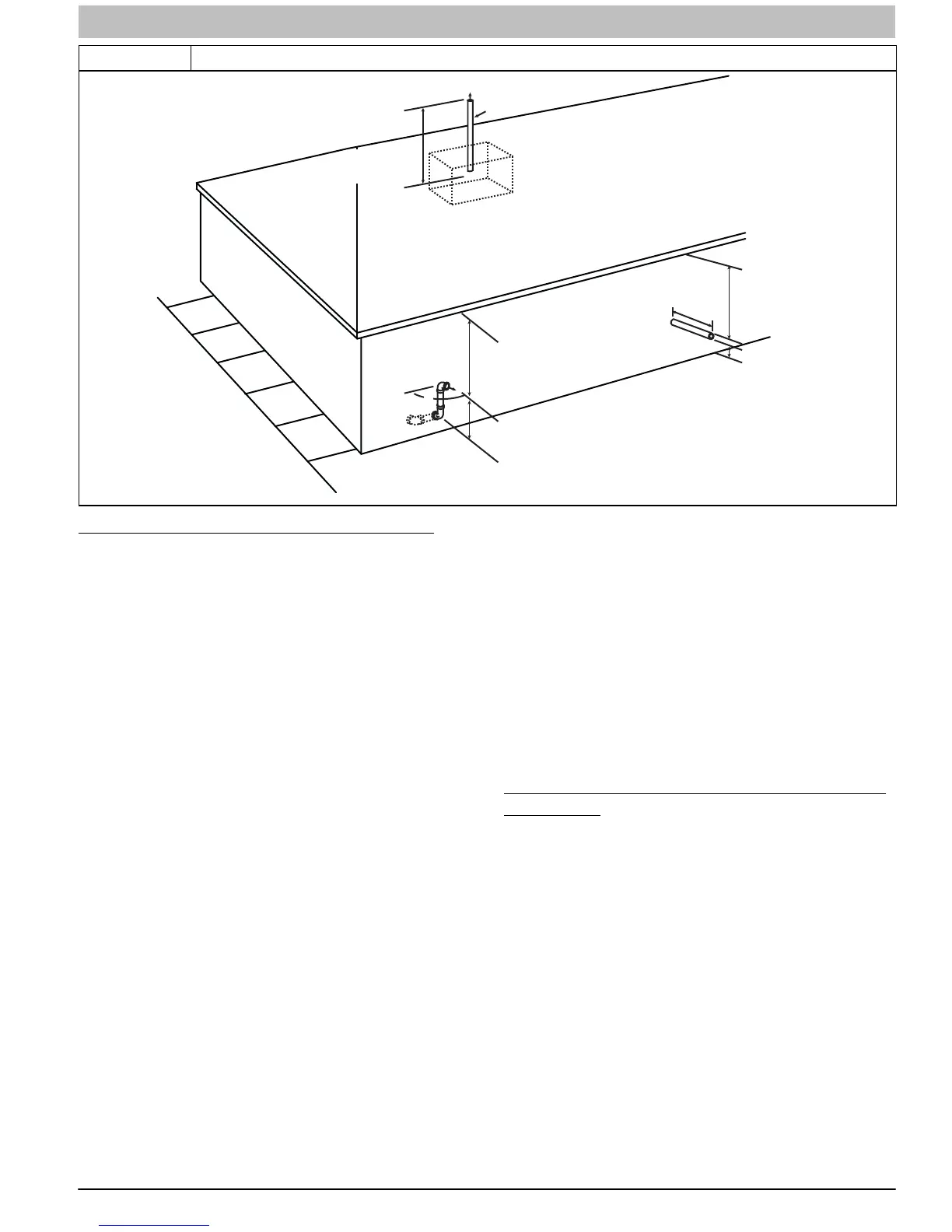
Figure 53 Vent Pipe Termination for Non−Direct Vent and Ventilated Combustion Air System
Abandoned masonry
used as raceway
(per code)
12 in. (305 mm) min. from
overhang or roof
Maintain 12 in. (305mm)
minimum clearance
above highest anticipated
snow level or grade
whichever is greater.
Side wall termination
with 2 elbows (preferred)
12 in. min. (305 mm)from
overhang or roof
Maintain 12 in. (305mm)
minimum clearance
above highest anticipated
snow level or grade
whichever is greater
6 in. (152mm) minimum clearance
between wall and end of vent pipe.
10 in. (254mm) maximum pipe length
Sidewall Termination
with Straight Pipe (preferred)
Roof Termination (Preferred)
Vent
Maintain 12 in .
minimum clearance
above highest anticipated
snow level maximum of
24 in. (610mm) above roof.
90°
(305mm)
A05091
Size the Vent and Combustion Air Pipes
General
Furnace combustion air and vent pipe connections are sized
for 2-in. (51 mm) pipe. Any pipe diameter change should be
made outside furnace casing in vertical pipe. Any change is
diameter to the pipe must be made as close to the furnace as
reasonably possible.
The Maximum Vent Length for the vent pipe and combustion air
pipe equals the Maximum Equivalent Vent Length (MEVL) in
Table 12 or Table 13, minus the number of fittings multiplied by
the deduction for each type of fitting used from Table 14.
The measured length of pipe used in a 2−pipe termination is
included in the total vent length. Include a deduction for a Tee
when used for Alberta and Saskatchewan terminations.
Concentric vent terminations, pipe lengths or elbows do not
require a deduction from the Maximum Equivalent Vent Length.
1. Measure the individual distance from the furnace to the
termination for each pipe.
2. Select a Maximum Equivalent Vent Length (MEVL)
longer than the measured distance of the individual vent
and combustion air connections to the vent termination.
3. Count the number of elbows for each pipe.
4. For each pipe, multiply the number of elbows by the
equivalent length for the type of elbow used. Record the
equivalent length of all the elbows for each pipe.
5. If a Tee is used on the termination, record the equivalent
length of the Tee used.
6. Record the equivalent length of the termination to be
used.
7. Subtract the equivalent lengths of the fittings and
terminations from the Maximum Equivalent Vent Length.
8. If the Maximum Vent Length calculated is longer than the
individual measured length of the vent pipe and
combustion air pipe, then the diameter of pipe selected
may be used.
9. If the Maximum Vent Length calculated is shorter than
the individual measured length of either the vent pipe or
the combustion air pipe, recalculate the Maximum Vent
Length using the next larger diameter pipe.
NOTE: The vent pipe and combustion air pipe must be the
same diameter.
NOTE: If the Maximum Vent Length for diameter of the pipe
selected is longer than the measured length and the equivalent
length of all the fitting and terminations, recalculate using the
next smaller diameter. If the recalculated Maximum Vent Length
is longer than the measured length of the vent pipe and
combustion air pipe, then that diameter of pipe selected may be
used.
When installing vent systems of short pipe lengths, use the
smallest allowable pipe diameter. Do not use pipe size greater
than required or incomplete combustion, flame disturbance, or
flame sense lockout may occur.
Combustion Air and Vent Piping Insulation
Guidelines
NOTE: Use closed cell, neoprene insulation or equivalent.
The vent pipe may pass through unconditioned areas. The
amount of exposed pipe allowed is shown in Table 15.
1. Using winter design temperature (used in load
calculations), find appropriate temperature for your
application and furnace model.
2. Determine the amount of total and exposed vent pipe.
3. Determine required insulation thickness for exposed pipe
length(s).
4. When combustion air inlet piping is installed above a
suspended ceiling, the pipe MUST be insulated with
moisture resistant insulation such as Armaflex or other
equivalent type of insulation.
5. Insulate combustion air inlet piping when run in warm,
humid spaces.
6. Install the insulation per the insulation manufacturer’s
installation instructions.
NOTE: Pipe length (ft / M) specified for maximum pipe lengths
located in unconditioned spaces (See Table 15) cannot exceed
total allowable pipe length as calculated from Table 12 or
Table 13.