CF Series Portable Chiller : Air & Water-Cooled : 5 - 40 Tons
Page: 48
TEMPTEK, INC.
525 East Stop 18 Road Greenwood, Indiana 46142
317-887-6352 Fax: 317-881-1277
Email: service@Temptek.com
5.5 PUMP SEAL SERVICE
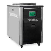
A. The coolant pump seal is a carbon/niresist
shaft seal assembly including a stationary
member, rotating member and tension
spring(gure5.5A).
B. The operator can determine the pump seal
isleakingwhenuidisidentiedleaking
from the pump case adapter. Generally, a
pump seal will leak due to inadequate unit
pressure,excessiveowandpooruid
quality.
C. The operator should follow this procedure to replace the
pump seal:
1. Disengage process operations according to the
procedure outlined in section 3.4. The operator
mustbecertainprocessuidtemperature
is under 100°F and pressure is relieved
(COOLANT pressure gauge reads “0”) and
watermake-upowisshutoffandallpressure
relieved.
2. Disengage main power supply. The operator
must verify the proper lockout procedures are
followed.
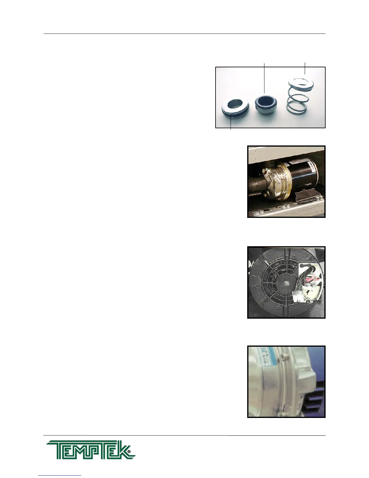
3. Access the pump motor by opening or removing
anycoverpanelsasnecessary(gure5.5B).
4. Drain machine. The machine can be drained
by using the drain valve located on the pump
case.Drainuidintoasuitablecontainerfor
reuseordisposalaccordingtomanufacturer’s
instructions (if a glycol solution is used).
5. Locate and remove the three motor wire leads
from the motor wiring terminals. The operator
should “map” the wire terminal locations to
ensure correct rewiring. The power cord should
beremovedfromthemotorhousing(gure
5.5C).
6. Locate and remove the pump casing bolts.
These bolts secure the motor and motor
adaptertothepumpcasing(gure5.5D).
7. Separate the motor and motor adapter from
the pump casing to expose the pump impeller
(gure5.5E).Removethemotorandmotor
Stationary member
Rotating Member Tension Spring
Figure 5.5A
Pump motor Figure 5.5B
Pump motor Figure 5.5C
Typical casing bolt Figure 5.5D