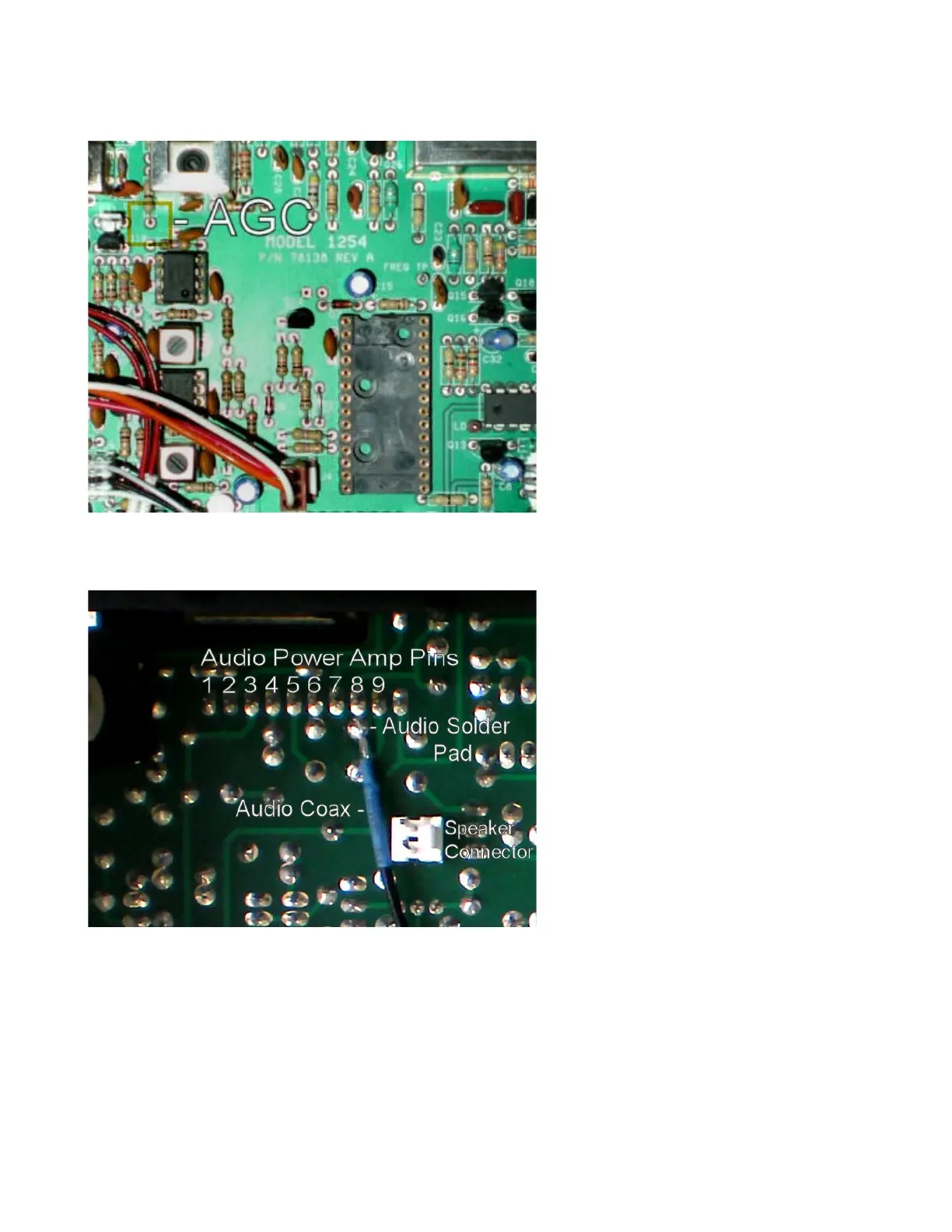
AGC Pickup Connection
The AGC voltage level from the radio's
main board is used to determine the
signal strength which is read over the
computer control interface. Take the
yellow wire with the two pin JST
connector and plug it into the auxiliary
board's two pin receptacle. Feed the
wire around the back of the radio main
board to the top side of the board.
Solder the free end of the yellow wire to
resistor R66, either side (see assembly
photos).
Audio Pickup Connection
Low level demodulated audio from
the radio is amplified and sampled
in the kit's new processor. The
shielded audio cable that was
plugged into X1 on the daughter
board and threaded through to the
bottom side of the radio's main
board needs to be soldered to the
main board. There is a row of what
looks like 10 pads in a row where
the audio power amplifier is
soldered on to the radio's main
board. Note that only 9 of these
pads go to the pins of the amplifier
chip. Observe the picture of the
bottom of the board around the
speaker connector and the notch for
the tuning encoder. Pin 8 is the solder point for the signal, center conductor, of the shielded
cable. Note that it is easier to solder to the pad just behind Pin 8.
On the processor daughter board insure that the coax connector does not twist left or right to
short any of the components on the daughter board. Plug in the speaker and reattach its
aluminum carrier panel to the radio chassis. Complete the installation by replacing the top and
bottom radio covers.