Do you have a question about the Ten-Tec 1253 and is the answer not in the manual?
Historical overview of regenerative receiver development and their place in radio history.
Explanation of the receiver's circuit operation, including block diagrams and key components.
Detailed list of all resistors, capacitors, inductors, semiconductors, and hardware included in the kit.
List of parts and tools not supplied but necessary or recommended for kit assembly and operation.
Guidelines for correctly installing electronic components onto the main circuit board, emphasizing common mistakes.
Step-by-step instructions for assembling and testing the audio amplifier stages of the receiver.
Instructions for installing components related to DC voltage regulation and control circuits.
Assembly steps for the RF amplifier, regenerative detector, and varactor tuning sections of the receiver.
Procedure to test the basic functionality of the receiver after initial assembly phases.
Instructions for assembling the electronic band switching control board, including component placement and soldering.
Installation of band switching components and wiring connections to the main receiver board.
Final assembly steps, including wiring, mounting components, and cabinet construction.
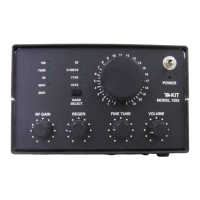
Description and usage of all front panel controls including RF Gain, Regeneration, Tuning, and Switches.
Explanation of the frequency coverage and typical transmissions for each of the nine tuning bands.
Supplementary information and considerations for instructors and advanced users of the T-KIT.
In-depth discussion on the circuit's RF regeneration and DC feedback mechanisms.
Specific advice for instructors regarding the T-KIT Model 1054, a related receiver.
| Modes | AM, SSB |
|---|---|
| Sensitivity | 0.5 µV for 10 dB S+N/N |
| Power Supply | 12 V DC |
| IF Frequencies | 455 kHz |
| Tuning Steps | 1 kHz, 100 Hz |
| Frequency Range | 500 kHz to 30 MHz |