How It Works:
An Introductory Circuit Description
A somewhat more technical explanation of your receiver is in the
Notes for Ham Club Leaders appendix. In the meantime, you can
follow the block diagram below, peek at the schematic diagram
which is the centerfold of this manual, the "glossary" of Helpful
Words and Abbreviations (pp. 13-14), and the following circuit
explanation.
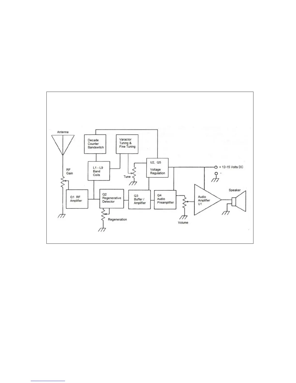
T-KIT Model No. 1253 Regenerative Receiver
Block Diagram
(A block diagram illustrates how major circuit sections are connected together
without showing all individual components as does the "schematic” diagram.)
To say it simply, a "detector" converts radio energy from an
antenna into audio energy, i.e., a sound which you can hear. A
detector can be as simple as a crystal diode, which is the heart
of the simple "crystal radio." If you've ever heard unwanted
radio signals on a stereo, telephone, PA system or intercom, you
can assume that some part of those devices has acted as a
detector to convert a nearby CB, taxi or broadcast signal into
intelligible sound. (This process of detection is also referred
to as demodulation.)
In the following explanation, the words regeneration, feedback
and oscillation all mean approximately the same thing.
1253 - 6
By itself, a detector can interpret or demodulate only very
strong signals such as a nearby AM radio station. However, the
process of regeneration can make a simple detector much more
sensitive by turning the detector into an "oscillating amplifier."
The regeneration circuit repeatedly feeds the detected signal
back to the input which boosts its strength many hundreds of
times. This feedback process must be carefully adjusted, which
is the important function of the regeneration control.
This receiver consists of an RF amplifier (Q11, a "regenerative"
detector/oscillator (Q2,Q3), an audio preamplifier (Q4), and an
integrated circuit audio amplifier (U1). Integrated circuit U2 is a
voltage regulator supplying a stable 8.0 volts to all circuits
except Q4 and U1. Transistor Q5 provides additional voltage
regulation for the varactor tuning circuit controlled by D10 and
for the detector/oscillator circuit.
Band switching is accomplished by the CD74HC4017 IC, a TTL
"decade counter" used in numerous digital logic circuits. It is
wired so that pressing the push button provides the "clock
pulse" needed to advance or "count" to the next output. The
voltage from a given output pin lights the corresponding LED and
powers the Q1/Q2 circuitry through the inductor selected.
Diodes D1-D9 are "PIN" diodes which pass DC voltage through
the band-selection inductors (L1-L9) while also stopping the RF
energy of Q1/Q2 from interfering with or being absorbed by the
switching circuit and power supply circuitry.
The frequency of oscillation is determined by the choice of
inductors (bandswitch), any capacitors used for C34-C42, and
the setting of the tuning controls. If the oscillator is tuned to 7
MHz, for example, any radio signal on that frequency will be
boosted and detected in the regeneration process. The resulting
output from transistor Q3 is a low-level audio signal which is
boosted by Q4 and further amplified to speaker level by the
TDA261 1A IC ("integrated circuit") amplifier.
The RF amplifier (Q1) serves two purposes. It boosts the RF
signals from the antenna to the detector, and it minimizes the
amount of oscillator RF going back out to the antenna.
Diodes D11 and D12 permit the use of an external DC power
supply with no need to remove the batteries.
1253 - 7