About the Receiver
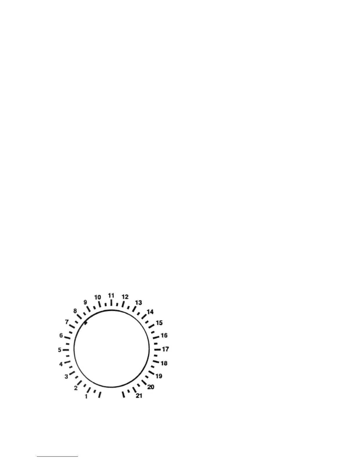
LOGGING SCALE
The "frequency display" of any communications equipment,
whether a mechanical dial or a digital-readout, is its costliest
single design feature. We chose the "Logging Scale" approach
to the calibration of the 1253 receiver because it is a proven
method of accurate frequency-finding each time you use the
receiver. Obviously, there is no room on the front panel to
provide attractively any frequency information about NINE
different bands.
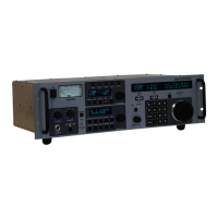
A classic example of practical logging-scale receivers used in
very serious situations is the National Radio "HRO" series of
receivers used throughout WWII. Even though some other
receivers had dials with frequency markings, the "HRO" was a
marvel of technical precision with its mechanical-digital 0-500
readout used in conjunction with frequency charts.
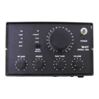
Frequency dials work well if there is some way to adjust a
receiver's components to match the dial. Other than the
adjustment required for R6 (regeneration trimmer), the 1253
receiver is designed to not require adjustment of variable coils or
capacitors for each band, the process called "alignment."
In addition to the sample Short Wave Listening log page provided
in this manual, we also provide the blank "Calibration Chart" on
the following page. You may wish to make extra copies of this
page before writing on it. ln the spaces provided, make notes of
known frequencies which correspond to any given Bandswitch
and Main Tuning combination.
In fact, you can use a
separate general coverage
receiver or ham transceiver
to listen for the 1253
receiver's oscillator signal
and then create a very
detailed frequency chart for
your receiver. An accurate
signal generator can be used
for the same purpose,
listening for its RF signal to
the 1253 receiver and
making notes on the chart.
1253 - 54
Model 1253 Band/Main Tuning Calibration Chart
DIAL 1 2 3 4 5 6 7 8 9
1.0
1.5
2.0
2.5
3.0
3.5
4.0
4.5
5.0
5.5
6.0
6.5
7.0
7.5
8.0
8.5
9.0
9.5
10.0
11.0
12.0
13.0
14.0
15.0
16.0
17.0
18.0
19.0
20.0
1253 - 55