Detail 3-44: Note on L10 and C43
These two components are additions to the original circuit: the
receiver works quite well without them. Adding L10 and C43
results in a significant boost in receiver sensitivity to weak
signals but also requires somewhat more careful adjustments of
the Regeneration Control. If this is your first experience with
regenerative receivers, we suggest that you omit L10 and C43
for now and gain real familiarity with the receiver's operation.
Consider adding these parts later if your listening interests begin
to include looking for weak CW or SSB signals on bands which
are nearly deserted because of time of day or sunspot conditions.
If those same bands are busy with strong signals, the receiver
works fine without L10 and C43, to the extent that the RF Gain
control setting will need to be reduced considerably.
The extra sensitivity offered by this circuit addition also can
permit the use of shorter antennas such as telescoping whips for
portable operation.
Adding L10 and C43 later will require a major dismantling of the
receiver, including removal of the subpanel installed in Step 3-36.
However, an easier approach is possible which also permits you
to try out the increased regeneration sensitivity without
committing to it permanently. For now, install C43 in the normal
manner. By itself, it will have no effect on receiver operation.
ln the position marked on the board for L10, solder two bare
wires extending about 1/2" above the board. Whenever you
wish, L10 can be soldered to these two wires after removing
only the top cover shell and battery shelf . This will allow you to
compare receiver performance with and without C43 and L10.
Inductor L10 is a 100 μH RF choke resembling the smaller
electrolytic capacitors but with no polarity stripe or one lead
being longer than the other. C43 is a .01 μF ceramic disc type.
Return to step 3-34 after deciding about L10 and C43.
1253 - 26
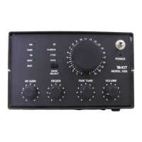
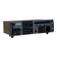
PHASE 4
Basic Receiver Operation Test
The purpose of this assembly phase is to let you verify that the
receiver indeed WORKS as the cumulative result of your good
work done in Phases 1, 2 and 3. We can do this by wiring in the
parts needed to tune around one popular and active band,
connecting antenna, speaker and DC voltage and then just play
with it for a while. For this test, we'll chose Band 4 (6.8 to 8.5
MHz.), a tuning range which includes the 40 meter amateur band
as well as numerous other transmissions. We will activate this
band by directly connecting the supply voltage intended for the
bandswitch control board. This test is not necessary if you prefer
to move ahead to complete receiver assembly: there will simply
be more details to troubleshoot if the receiver does not perform
as specified.
4-1. Install molded coil L4, 8.2 μH (gray-red-gold-gold).
4-2. Install C23, a .01 μF " MYLAR" capacitor marked 103.
4-3. Install D4, one of the 9 tiny 1SS135 PIN diodes in your
kit, making sure that its banded cathode end is oriented as
outlined on the board (i.e., pointing toward C29/Q5).
4-4. Prepare a 3" length of RED hookup wire and solder one
end to "X" near Q5.
4-5. Solder the other end of the red hookup wire (4-4) to the
rearmost pad for " C37 " (a capacitor position NOT used in the
standard version of this receiver.) This wire connection has the
effect of a temporary +8VDC connection to the "Band 4" point.
4-6. Reconnect the white and black "AUDIO OUT" wires to
the speaker per 1-32.
4-7. Connect an outdoor antenna or at least 10' of hookup
wire to the center conductor of the coax cable.
4-8. Turn ALL panel controls completely to the left.
4-9. Re-connect 11-15 volts DC to the red and black wires
used in the Phase 1 test.
4-10. Turn the volume control fully clockwise and then back
to its middle position. With all other controls turned to the left,
you should hear only a soft hiss during volume control rotation.
1253 - 27