15
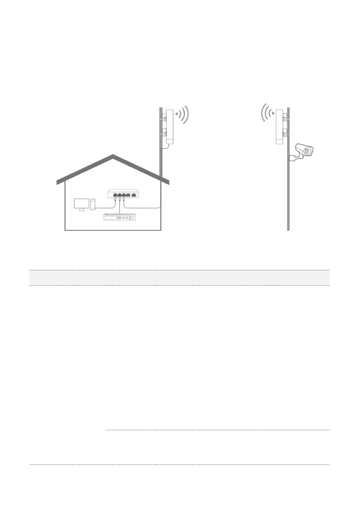
receiver in the open air at the point where the IP camera is located.
Step 2 Uncover the housings of the two CPEs, and connect the PoE/LAN/WAN ports of the CPEs
to PoE injectors respectively. The LAN/WAN LED indicators light up.
Step 3 Adjust the two CPEs’ direction or location until the LED1, LED2 and LED3 of the two CPEs
light up.
Step 4 Use the plastic straps to attach the two CPEs to the poles respectively.
Check the LED1, LED2 and LED3 indicators of the CPEs to confirm whether the positions are
proper. The more LED indicators light up, and the better the connection quality is. The LED
indicator descriptions of the CPEs below are for reference.
LED1, LED2, LED3
(Received signal strength
LED indicators)
There is device connected to the CPE.
Solid on: The CPE may work in AP, Repeater, P2MP or Router
mode.
Blinking: The CPE may work in Client, Universal Repeater or
WISP mode.
Each LED indicator corresponds to a received signal
strength value. When the received signal strength of the
CPE reaches the RSSI threshold, the corresponding LED
indicator lights up. You can judge the connection quality
based on the statuses of the LED indicators.
By default, the minimum signal strength of LED1, LED2
and LED3 are -90 dBm, -80 dBm and -70 dBm. You can
change them on the Wireless > Advanced page of the
web UI of the CPE.
No device is connected to the CPE, or the received signal
strength is less than the RSSI threshold (default: -90
dBm).
 Loading...