14
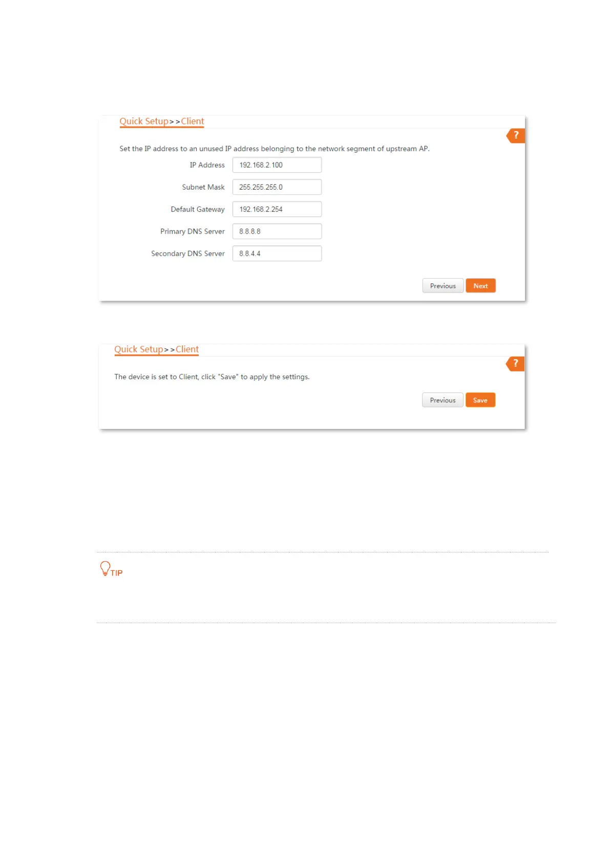
6. Set the IP address to an unused IP address belonging to the same network segment as that
of CPE1. For example, if the IP address of CPE1 is 192.168.2.1, you can set this CPE’s IP
address to 192.168.2.X (X ranges from 2 to 254). Then click Next.
7. Click Save, and wait until the CPE reboots to activate the settings.
----End
When LED1, LED2, and LED3 of CPE1 are solid on, and LED1, LED2, and LED3 of CPE2 are blinking,
the bridging succeeds.
If you want to perform peer-to-multiple peers bridging, refer to Step 4 to bridge them to the WiFi
network of the CPE with the LED1, LED2 and LED3 indicators solid on.
You can check the SSID and key of the CPE1 or CPE2 by choosing Wireless > Basic after logging in to the
web UI.
1.2.3 Instal the CPEs
The CPE (transmitter in AP mode) with LED1, LED2 and LED3 solid on should be connected to the
switch connecting to a network video recorder (NVR). See Figure 1 below.
The CPE (receiver in Client mode) with LED1, LED2 and LED3 blinking should be connected to the
switch connecting to a monitoring IP camera. See Figure 2 below.
Detailed procedures are as follows:
Step 1 Place the transmitter in the open air at the point where the NVR is located. Place the
 Loading...