4
OPERATION
AC/DC Voltage Measurements
• Set the function switch to VAC or VDC position.
• Insert the black test lead into the negative COM terminal and the red test lead into
the positive V terminal.
• Connect the test leads in parallel to the circuit under test.
• Read the voltage measurement on the LCD display.
CAUTION: Do not measure AC/ DC voltages if a motor on the circuit is being switched
ON or OFF. Large voltage surges may occur that can damage the meter.
AC/DC Current Measurements
• Set the function switch to the µA/mA position.
• Insert the black test lead into the negative COM terminal and the red test lead into
the positive µA/mA terminal.
• For current measurements up to 2000µA DC/AC, set the function switch to the mA
position.
• Press the MODE button to indicate “DC” / “AC” on the display.
• Remove power from the circuit under test, then open up the circuit at the point
where you wish to measure current.
• Touch the black test probe tip to the negative side of the circuit. and the red test
probe tip to the positive side of the circuit and apply power to the circuit.
• Read the current in the display
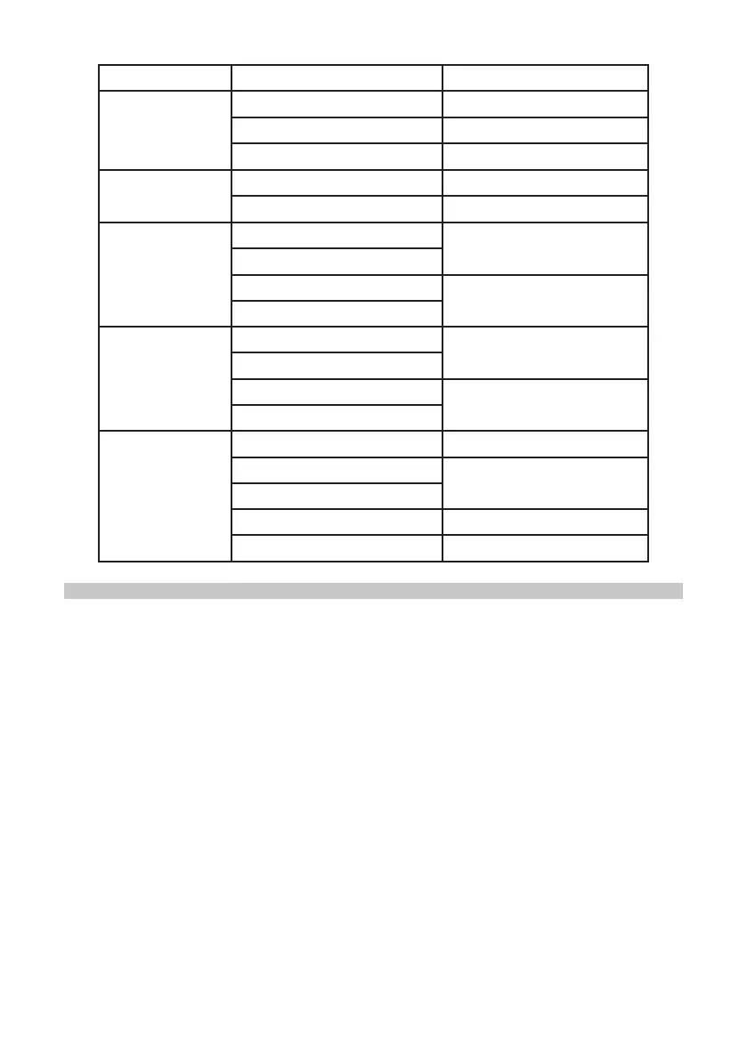
Function Range Accuracy
DC Voltage
200mV
±(0.5%+3)
2.000V - 20.00V
±(1.0%+3)
200.0V - 500V
±(1.0%+3)
AC Voltage
50-60Hz
2.000V - 20.00V
±(1.0%+5)
200.0V - 500V
±(1.0%+10)
DC Current
200.0µA
±(1.5%+3)
2000µA
20.00mA
±(2.0%+3)
200.0mA
AC Current
200.0µA
±(1.8%+8)
2000µA
20.00mA
±(2.5%+8)
200.0mA
Resistance
200.0Ω
±(0.8%+5)
2.000kΩ
±(1.2%+3)
20.00kΩ - 200.0kΩ
2.000MΩ
±(2.0%+8)
20.00MΩ
±(5.0%+8)